NB671, 24V, HIGH CURRENT SYNCHRONOUS STEP-DOWN CONVERTER
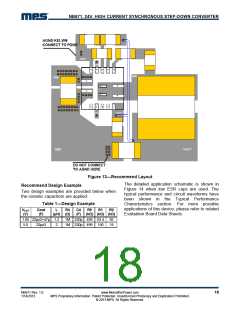
Figure 13—Recommend Layout
The detailed application schematic is shown in
Figure 14 when low ESR caps are used. The
typical performance and circuit waveforms have
been shown in the Typical Performance
Characteristics section. For more possible
applications of this device, please refer to related
Evaluation Board Data Sheets.
Recommend Design Example
Two design examples are provided below when
the ceramic capacitors are applied:
Table 1—Design Example
VOUT
(V)
Cout
(F)
L
R4
(μH) (Ω)
1M 220p 499 63.4
1M 220p 499 150
C4
R9
R1
R2
(F) (kΩ) (kΩ) (kΩ)
1.05 22μx2+47μ 1.2
5.0 22μx3
82
18
2
NB671 Rev. 1.0
1/14/2013
www.MonolithicPower.com
MPS Proprietary Information. Patent Protected. Unauthorized Photocopy and Duplication Prohibited.
© 2013 MPS. All Rights Reserved.
18

 MPS [ MONOLITHIC POWER SYSTEMS ]