Freescale Semiconductor, Inc.
M
P
X
Y
8
0
2
0
A
APPLICATIONS
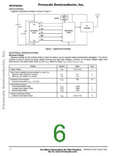
Suggested application example is shown in Figure 7.
Mo t io n
S en se
O p ti on a l
+
S 1
S 0
V
D
D
RF
Tra n smi tt e r
3 .0
V
D ata
C LK
R ST
S t at e Ma ch in e
o r MC U
M PX Y8 020 A
S enso r
0 .1 µF
O UT
V
S
S
Figure 7. Application Example
ELECTRICAL SPECIFICATIONS
Maximum Ratings
Maximum ratings are the extreme limits to which the device can be exposed without permanently damaging it. The device
contains circuitry to protect the inputs against damage from high static voltages; however, do not apply voltages higher than
those shown in the table below. Keep VIN and VOUT within the range VSS ≤ (VIN or VOUT) ≤ VDD
.
Rating
Symbol
Value
Unit
Supply Voltage
V
DD
–0.3 to +4.0
V
Short Circuit Capability (all pins excluding V and V
)
DD
SS
Maximum High Voltage for 5 minutes
Minimum Low Voltage for 5 minutes
V
SC
V
SC
V
V
V
V
DD
SS
Substrate Current Injection
I
600
µA
SUB
Current from any pin to V – 0.3 VDC)
SS
Electrostatic Discharge
Human Body Model (HBM)
Charged Device Model (CDM)
Machine Model (MM)
V
ESD
V
ESD
V
ESD
±1000
±1000
±200
V
V
V
Storage Temperature Range
Standard Temperature Range
T
stg
–40 to +150
°C
6
Motorola Sensor Device Data
For More Information On This Product,
Go to: www.freescale.com

 MOTOROLA [ MOTOROLA ]