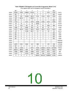
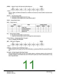
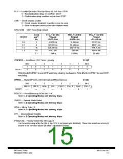
HPRIO — Highest Priority I-Bit Interrupt and Miscellaneous
$103C
Bit 7
6
5
4
3
PSEL3
0
2
PSEL2
1
1
PSEL1
0
Bit 0
PSEL0
1
RBOOT SMOD
MDA
—
IRV
—
RESET:
—
—
RBOOT, SMOD, and MDA reset depend on conditions at reset and can only be written in special modes
(SMOD = 1).
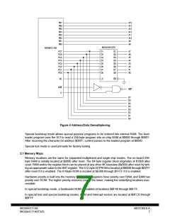
RBOOT — Read Bootstrap ROM
0 = Bootloader ROM disabled and not in map
1 = Bootloader ROM enabled and in map at $BF40–$BFFF
SMOD —Special Mode Select
MDA — Mode Select A
Inputs
Mode
Latched at Reset
MODB
MODA
RBOOT
SMOD
MDA
1
1
0
0
0
1
0
1
Single Chip
0
0
1
0
0
0
1
1
0
1
0
1
Expanded Multiplexed
Special Bootstrap
Special Test
IRV — Internal Read Visibility
0 = No internal read visibility on external bus
1 = Data from internal reads is driven out through the external data bus
PSEL3–PSEL0 — Priority Select Bits 3 through 0
Refer to 3 Resets and Interrupts.
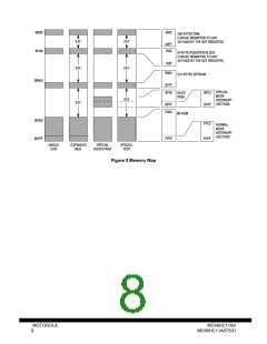
INIT — RAM and I/O Mapping
$103D
Bit 7
RAM3
0
6
RAM2
0
5
RAM1
0
4
RAM0
0
3
REG3
0
2
REG2
0
1
REG1
0
Bit 0
REG0
1
RESET:
RAM[3:0] —256-Byte Internal RAM Map Position
RAM[3:0] determine the upper four bits of the RAM address, positioning RAM at the selected 4K bound-
ary.
REG[3:0] —64-Byte Register Block Map Position
REG[3:0] determine the upper four bits of the register address, positioning registers at the selected 4K
boundary. Register can be written only once in the first 64 cycles out of reset in normal modes, or any
time in special modes.
MC68HC11A8
MC68HC11A8TS/D
MOTOROLA
11

 MOTOROLA [ MOTOROLA ]