3 Resets and Interrupts
The MC68HC11A8 has three reset vectors and 18 interrupt vectors. The reset vectors are as follows:
• RESET, or Power-On
• COP Clock Monitor Fail
• COP Failure
The eight interrupt vectors service 23 interrupt sources (three non-maskable, 20 maskable). The three
non-maskable interrupt vectors are as follows:
• Illegal Opcode Trap
• Software Interrupt
• XIRQ Pin (Pseudo Non-Maskable Interrupt)
The 20 maskable interrupt sources are subject to masking by a global interrupt mask, the I bit in the
condition code register (CCR). In addition to the global I bit, all of these sources except the external
interrupt (IRQ) pin are controlled by local enable bits in control registers. Most interrupt sources in the
M68HC11 have separate interrupt vectors. For this reason, there is usually no need for software to poll
control registers to determine the cause of an interrupt. The maskable interrupt sources respond to a
fixed priority relationship, except that any one source can be dynamically elevated to the highest priority
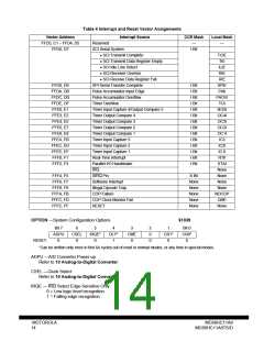
position of any maskable source. Refer to the table of interrupt and reset vector assignments.
On-chip peripheral systems generate maskable interrupts that are recognized only if the I bit in the CCR
is clear. Maskable interrupts are prioritized according to a default arrangement, but any one source can
be elevated to the highest maskable priority position by the HPRIO register. The HPRIO register can be
written at any time, provided the I bit in the CCR is set.
For some interrupt sources, such as the parallel I/O and SCI interrupts, the flags are automatically
cleared during the course of responding to the interrupt requests. For example, the RDRF flag in the
SCI system is cleared by the automatic clearing mechanism, which consists of a read of the SCI status
register while RDRF is set, followed by a read of the SCI data register. The normal response to an
RDRF interrupt request is to read the SCI status register to check for receive errors, then to read the
received data from the SCI data register. These two steps satisfy the automatic clearing mechanism
without requiring any special instructions.
The real-time interrupt (RTI) function generates hardware interrupts at a fixed periodic rate. These hard-
ware interrupts provide a time reference signal for routines that measure real time. The routine notes
the number of times a particular interrupt has occurred and multiplies that number by the predetermined
subroutine execution time.
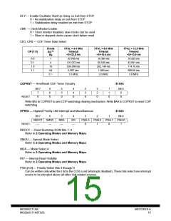
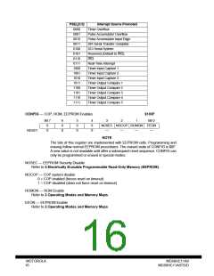
There are four RTI signal rates available in the MC68HC11A8. The MCU oscillator frequency and the
value of two software-accessible control bits, RTR1 and RTR0, in the pulse accumulator control register
(PACTL) determine these signal rates. Refer to 8 Main Timer for more information about PACTL.
MC68HC11A8
MC68HC11A8TS/D
MOTOROLA
13

 MOTOROLA [ MOTOROLA ]