MITSUBISHI MICROCOMPUTERS
M37270MF-XXXSP
M37270EF-XXXSP, M37270EFSP
SINGLE-CHIP 8-BIT CMOS MICROCOMPUTER with CLOSED CAPTION DECODER
and ON-SCREEN DISPLAY CONTROLLER
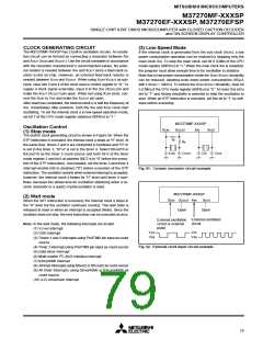
RESET CIRCUIT
The M37270MF-XXXSP is reset according to the sequence shown
in Figure 87. It starts the program from the address formed by using
the content of address FFFF16 as the high-order address and the
content of the address FFFE16 as the low-order address, when the
RESET pin is held at “L” level for 2 ms or more while the power source
voltage is 5 V ± 10 % and the oscillation of a quartz-crystal oscillator
or a ceramic resonator is stable and then returned to “H” level. The
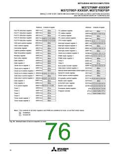
internal state of microcomputer at reset are shown in Figure 88.
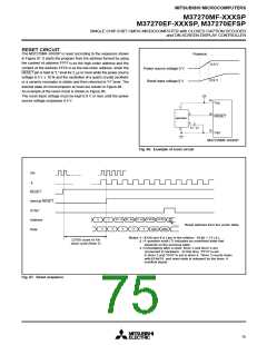
An example of the reset circuit is shown in Figure 86.
Poweron
4.5 V
0.9 V
Power source voltage 0 V
Reset input voltage 0 V
The reset input voltage must be kept 0.9 V or less until the power
source voltage surpasses 4.5 V.
33
Vcc
1
36
5
4
RESET
M51953AL
0.1
F
3
32
Vss
M37270MF-XXXSP
Fig. 86. Example of reset circuit
XIN
φ
RESET
Internal RESET
SYNC
ADH,
01, S-2 FFFE FFFF
ADL
01, S-1
01, S
?
?
Address
Data
Reset address from the vector table
ADL AD
H
?
?
?
?
?
Notes 1 : f(XIN) and f( φ ) are in the relation : f(XIN) = 2·f ( φ ).
32768 count of XIN
clock cycle (Note 3)
A question mark (?) indicates an undefined state that
depends on the previous state.
2 :
3 : Immediately after a reset, timer 3 and timer 4 are
connected in hardware. At this time, “FF16” is set
in timer 3 and “0716” is set to timer 4. Timer 3 counts down
withf(XIN)/16, and reset state is released by the timer 4
overflow signal.
Fig. 87. Reset sequence
75

 MITSUBISHI [ Mitsubishi Group ]