MITSUBISHI MICROCOMPUTERS
M37270MF-XXXSP
M37270EF-XXXSP, M37270EFSP
SINGLE-CHIP 8-BIT CMOS MICROCOMPUTER with CLOSED CAPTION DECODER
and ON-SCREEN DISPLAY CONTROLLER
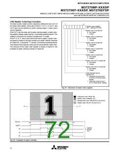
(16) Raster Coloring Function
An entire screen (raster) can be colored by setting the bits 6 to 0 of
the raster color register. Since each of the R, G, B, I1, I2, OUT1, and
OUT2 pins can be switched to raster coloring output, 7 raster colors
can be obtained.
7
0
Raster color register
(RC : address 021816
)
Raster color R control bit
0 : No output
1 : Output
If the OUT1 pin has been set to raster coloring output, a raster color-
ing signal is always output during 1 horizontal scanning period. This
setting is necessary for erasing a background TV image.
If the R, G, B, I1, and I2 pins have been set to output, a raster color-
ing signal is output in the part except a no-raster colored character
(in Figure 82, a character “1”) during 1 horizontal scanning period.
This ensures that character colors are not mixed with the raster color.
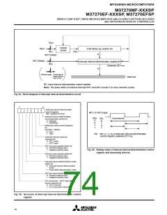
The structure of the raster color register is shown in Figure 81, the
example of raster coloring is shown in Figure 82.
Raster color G control bit
0 : No output
1 : Output
Raster color B control bit
0 : No output
1 : Output
Raster color I1 control bit
0 : No output
1 : Output
Raster color I2 control bit
0 : No output
1 : Output
Raster color OUT1 control bit
0 : No output
1 : Output
Raster color OUT2 control bit
0 : No output
1 : Output
OSD interrupt source
selection bit
0 : Interrupt occurs at end
of OSD or EXOSD block
display
1 : Interrupt occurs at end
of CC mode block display
Fig. 81. Structure of raster color register
: Character color “RED” (R)
: Border color “GREEN” (G)
: Background color “MAGENTA” (R and B)
: Raster color “BLUE” (R and OUT1)
A'
A
HSYNC
OUT1
Signals
across
A-A'
R
G
B
Fig. 82. Example of raster coloring
72

 MITSUBISHI [ Mitsubishi Group ]