MITSUBISHI MICROCOMPUTERS
M37270MF-XXXSP
M37270EF-XXXSP, M37270EFSP
SINGLE-CHIP 8-BIT CMOS MICROCOMPUTER with CLOSED CAPTION DECODER
and ON-SCREEN DISPLAY CONTROLLER
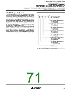
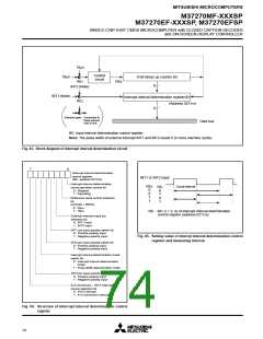
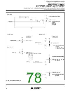
16µs
Control
circuit
32µs
8-bit binary up counter (8)
RE1
RE0
8
INT2 (Note)
INT1 (Note)
Interrupt interval determination register(8)
RE2
(Address 021116)
8
Selection gate :
Connected to
black colored
side at rest.
Data bus
RE: Input interval determination control register
Note: The pulse width of external interrupt INT1 and INT2 needs 5 or more machine cycles.
Fig. 83. Block diagram of interrupt interval determination circuit
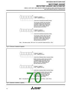
7
0
Interrupt interval determination
control register
(RE : address 021216
INT1 or INT2 input
)
Interrupt interval determination
circuit operation control bit
0 : Stopped
RE5
0
0
1
1
Count interval
REi
0
1
0
1
1 : Operating
Reference clock control selection
bit
(at f(XIN) = 8MHz)
0 : 32µs
1 : 16µs
REi : Bit i (i = 3, 4) of interrupt interval determination
control register (address 021116)
External interrupt input pin
selection bit
0 : INT1 input
1 : INT2 input
INT1 pin input polarity switch bit
0 : Positive polarity input
1 : Negative polarity input
Fig. 85. Setting value of interrpt interval determination control
register and measuring interval
INT2 pin input polarity switch bit
0 : Positive polarity input
1 : Negative polarity input
Interrupt interval determination mode
switch bit
0 : Interrupt interval determination
mode
1 : Pulse width determination mode
INT3 pin input polarity switch bit
0 : Positive polarity input
1 : Negative polarity input
A-D conversion INT3 interrupt
•
source selection bit
0 : INT3 interrupt
1 : A-D conversion interrupt
Fig. 84. Structure of interrupt interval determination control
register
74

 MITSUBISHI [ Mitsubishi Group ]