MITSUBISHI MICROCOMPUTERS
M37270MF-XXXSP
M37270EF-XXXSP, M37270EFSP
SINGLE-CHIP 8-BIT CMOS MICROCOMPUTER with CLOSED CAPTION DECODER
and ON-SCREEN DISPLAY CONTROLLER
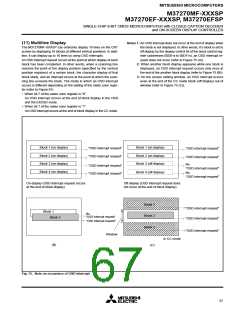
(13) Scan Mode
M37270MF-XXXSP has the bi-scan mode for corresponding to HSYNC
of double speed frequency. In the bi-scan mode, the vertical start
display position and the vertical size is two times as compared with
the normal scan mode. The scan mode is selected by bit 1 of the
OSD control register (refer to Figure 49).
Table 19. Setting for scan mode
Bi-scan
Scan mode
Normal scan
Parameter
1
Bit 1 of OSD control register
0
Value of vertical position register ✕ 1H
1TC ✕ 1/2H
Value of vertical position register ✕ 2H
Vertical display start position
Vertical dot size
1TC ✕ 1H
1TC ✕ 2H
2TC ✕ 4H
3TC ✕ 6H
1TC ✕ 1H
2TC ✕ 2H
3TC ✕ 3H
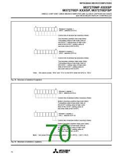
Notes 1: Set values except “0016” and “0116” to the window H regis-
ter 1 when the window H register 2 is “0016.”
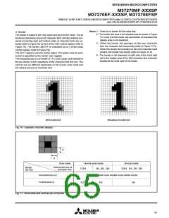
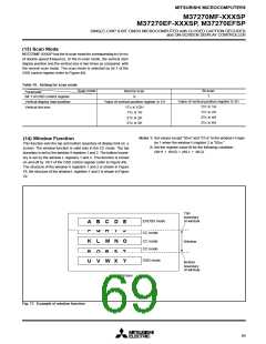
(14) Window Function
This function sets the top and bottom boundary of display limit on a
screen. The window function is valid only in the CC mode. The top
boundary is set by the window H registers 1 and 2. The bottom bound-
ary is set by the window L registers 1 and 2. This function is turned
on and off by bit 5 of the OSD control register (refer to Figure 49).
The structure of the window H registers 1 and 2 is shown in Figure
78, the structure of the window L registers 1 and 2 is shown in Figure
79.
2: Set the register value fit for the following condition :
(WH1 + WH2) < (WL1 + WL2)
Top
boundary
of window
EXOSD mode
CC mode
A B C D E
F G H
I
J
CC mode
CC mode
K L M N O
Window
P Q R S T
U V W X Y
OSD mode
Bottom
boundary
of window
Screen
Fig. 77. Example of window function
69

 MITSUBISHI [ Mitsubishi Group ]