Mitsubishi microcomputers
M16C / 61 Group
SINGLE-CHIP 16-BIT CMOS MICROCOMPUTER
Bus Settings
Bus Settings
The BYTE pin and bits 4 to 6 of the processor mode register 0 (address 000416) are used to change the bus
settings.
Table 1.10.1 shows the factors used to change the bus settings.
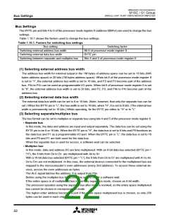
Table 1.10.1. Factors for switching bus settings
Bus setting
Switching factor
Bit 6 of processor mode register 0
BYTE pin
Switching external address bus width
Switching external data bus width
Switching between separate and multiplex bus
Bits 4 and 5 of processor mode register 0
(1) Selecting external address bus width
The address bus width for external output in the 1M bytes of address space can be set to 16 bits (64K
bytes address space) or 20 bits (1M bytes address space). When bit 6 of the processor mode register 0
is set to “1”, the external address bus width is set to 16 bits, and P2 and P3 become part of the address
bus. P40 to P43 can be used as programmable I/O ports. When bit 6 of processor mode register 0 is set
to “0”, the external address bus width is set to 20 bits, and P2, P3, and P40 to P43 become part of the
address bus.
(2) Selecting external data bus width
The external data bus width can be set to 8 or 16 bits. (Note, however, that only the separate bus can be
set.) When the BYTE pin is “L”, the bus width is set to 16 bits; when “H”, it is set to 8 bits. (The internal bus
width is permanently set to 16 bits.) While operating, fix the BYTE pin either to “H” or to “L”.
(3) Selecting separate/multiplex bus
The bus format can be set to multiplex or separate bus using bits 4 and 5 of the processor mode register 0.
• Separate bus
In this mode, the data and address are input and output separately. The data bus can be set using the
BYTE pin to be 8 or 16 bits. When the BYTE pin is “H”, the data bus is set to 8 bits and P0 functions as
the data bus and P1 as a programmable I/O port. When the BYTE pin is “L”, the data bus is set to 16
bits and P0 and P1 are both used for the data bus.
When the separate bus is used for access, a software wait can be selected.
• Multiplex bus
In this mode, data and address I/O are time multiplexed. With an 8-bit data bus selected (BYTE pin =
“H”), the 8 bits from D0 to D7 are multiplexed with A0 to A7.
With a 16-bit data bus selected (BYTE pin = “L”), the 8 bits from D0 to D7 are multiplexed with A1 to A8.
D8 to D15 are not multiplexed. In this case, the external devices connected to the multiplexed bus are
mapped to the microcomputer’s even addresses (every 2nd address). To access these external de-
vices, access the even addresses as bytes.
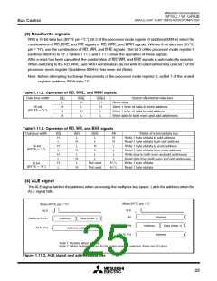
The ALE signal latches the address. It is output from P56.
Before using the multiplex bus for access, be sure to insert a software wait.
If the entire space is of multiplexed bus in memory expansion mode, choose an 8-bit width.
The processor operates using the separate bus after reset is revoked, so the entire space multiplexed
bus cannot be chosen in microprocessor mode.
The higher-order address becomes a port if the entire space multiplexed bus is chosen, so only 256
bytes can be used in each chip select.
22

 MITSUBISHI [ Mitsubishi Group ]