Mitsubishi microcomputers
M16C / 61 Group
SINGLE-CHIP 16-BIT CMOS MICROCOMPUTER
Software Reset
Software Reset
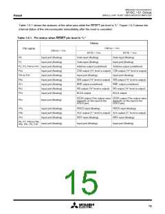
Writing “1” to bit 3 of the processor mode register 0 (address 000416) applies a (software) reset to the
microcomputer. A software reset has almost the same effect as a hardware reset. The contents of internal
RAM are preserved.
Processor Mode
(1) Types of Processor Mode
One of three processor modes can be selected: single-chip mode, memory expansion mode, and micro-
processor mode. The functions of some pins, the memory map, and the access space differ according to
the selected processor mode.
• Single-chip mode
In single-chip mode, only internal memory space (SFR, internal RAM, and internal ROM) can be
accessed. Ports P0 to P10 can be used as programmable I/O ports or as I/O ports for the internal
peripheral functions.
• Memory expansion mode
In memory expansion mode, external memory can be accessed in addition to the internal memory
space (SFR, internal RAM, and internal ROM).
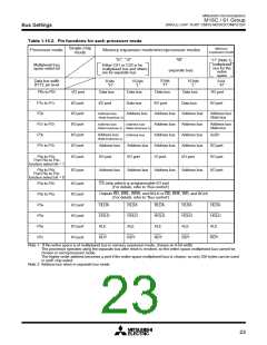
In this mode, some of the pins function as the address bus, the data bus, and as control signals. The
number of pins assigned to these functions depends on the bus and register settings. (See “Bus
Settings” for details.)
• Microprocessor mode
In microprocessor mode, the SFR, internal RAM, and external memory space can be accessed. The
internal ROM area cannot be accessed.
In this mode, some of the pins function as the address bus, the data bus, and as control signals. The
number of pins assigned to these functions depends on the bus and register settings. (See “Bus
Settings” for details.)
(2) Setting Processor Modes
The processor mode is set using the CNVSS pin and the processor mode bits (bits 1 and 0 at address
000416). Do not set the processor mode bits to “102”.
Regardless of the level of the CNVSS pin, changing the processor mode bits selects the mode. Therefore,
never change the processor mode bits when changing the contents of other bits. Also do not attempt to
shift to or from the microprocessor mode within the program stored in the internal ROM area.
• Applying VSS to CNVSS pin
The microcomputer begins operation in single-chip mode after being reset. Memory expansion mode
is selected by writing “012” to the processor mode is selected bits.
• Applying VCC to CNVSS pin
The microcomputer starts to operate in microprocessor mode after being reset.
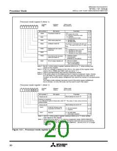
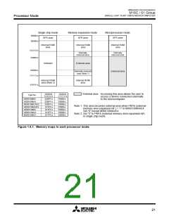
Figure 1.8.1 shows the processor mode register 0 and 1. Figure 1.9.1 shows the memory maps appli-
cable for each of the modes.
19

 MITSUBISHI [ Mitsubishi Group ]