Preliminary Information
MT93L16
4
Howling Detector (HWLD)
(4. Patent Pending)
The AGC can be disabled by setting the AGC- bit to
1 in MC control register.
The Howling detector is part of an Anti-Howling
control, designed to prevent oscillation as a result of
positive feedback in the audio paths.
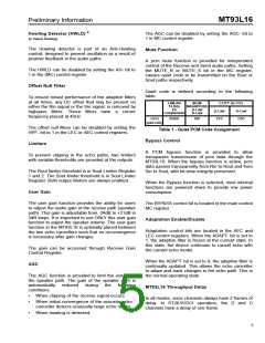
Mute Function
A pcm mute function is provided for independent
control of the Receive and Send audio paths. Setting
the MUTE_R or MUTE_S bit in the MC register,
causes quiet code to be transmitted on the Rout or
Sout paths respectively.
The HWLD can be disabled by setting the AH- bit to
1 in the (MC) control register.
Offset Null Filter
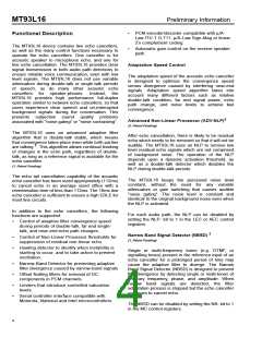
Quiet code is defined according to the following
table.
To ensure robust performance of the adaptive filters
at all times, any DC offset that may be present on
either the Rin signal or the Sin signal, is removed by
LINEAR
16 bits
SIGN/
MAGNITUDE
µ-Law
CCITT (G.711)
2’s
µ-Law
FFh
A-Law
highpass filters. These filters have
frequency placed at 40Hz.
a
corner
complement
A-Law
+Zero
0000h
80h
D5h
(quiet code)
The offset null filters can be disabled by setting the
HPF- bit to 1 in the LEC or AEC control registers.
Table 1 - Quiet PCM Code Assignment
Bypass Control
Limiters
A PCM bypass function is provided to allow
transparent transmission of pcm data through the
MT93L16. When the bypass function is active, pcm
data passes transparently from Rin to Rout and from
Sin to Sout, with bit-wise integrity preserved.
To prevent clipping in the echo paths, two limiters
with variable thresholds are provided at the outputs.
The Rout limiter threshold is in Rout Limiter Register
1 and 2. The Sout limiter threshold is in Sout Limiter
Register. Both output limiters are always enabled.
When the Bypass function is selected, most internal
functions are powered down to provide low power
consumption.
User Gain
The user gain function provides the ability for users
to adjust the audio gain in the receive path (speaker
path). This gain is adjustable from -24dB to +21dB in
3dB steps. It is important to use ONLY this user gain
function to adjust the speaker volume. The user gain
function in the MT93L16 is optimally placed between
the two echo cancellers such that no reconvergence
is necessary after gain changes.
The BYPASS control bit is located in the main control
MC register.
Adaptation Enable/Disable
Adaptation control bits are located in the AEC and
LEC control registers. When the ADAPT- bit is set to
1, the adaptive filter is frozen at the current state. In
this state, the device continues to cancel echo with
the current echo model.
The gain can be accessed through Receive Gain
Control Register.
When the ADAPT- bit is set to 0, the adaptive filter is
continually updated. This allows the echo canceller
to adapt and track changes in the echo path. This is
the normal operating state.
AGC
The AGC function is provided to limit the volume in
the speaker path. The gain of the speaker path is
automatically
conditions:
reduced
during
the
following
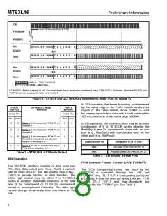
MT93L16 Throughput Delay
•
•
When clipping of the receive signal occurs.
In all modes, voice channels always have 2 frames of
delay. In ST-BUS/GCI operation, the D and C
channels have a delay of one frame.
When initial convergence of the acoustic echo
canceller detects unusually large echo return.
•
When howling is detected.
5

 MITEL [ MITEL NETWORKS CORPORATION ]