Preliminary Information
MT93L16
C4i
start of frame (stbus & GCI)
F0i (ST-BUS)
F0i (GCI)
0
1
2
3
4
B
PORT1
Rin
7 6 5 4 3 2 1 0
EC
Sout
7 6 5 4 3 2 1 0
PORT2
Sin
7 6 5 4 3 2 1 0
EC
7 6 5 4 3 2 1 0
Rout
outputs = High impedance
inputs = don’t care
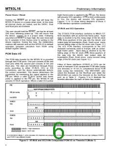
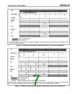
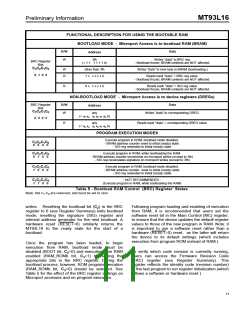
In ST-BUS/GCI Mode 2, echo canceller I/O channels are assigned to ST-BUS/GCI timeslot 2. Note that the user can configure PORT1
and PORT2 into different modes.
Figure 4 - ST-BUS and GCI 8-Bit Companded PCM I/O on Timeslot 2 (Mode 2)
C4i
start of frame (stbus & GCI)
F0i (ST-BUS)
0
1
2
3
4
B
C
D
F0i (GCI)
PORT1
7 6 5 4 3 2 1 0 7 6 5 4 3 2 1 0 7 6 5 4 3 2 1 0
Rin
EC
7 6 5 4 3 2 1 0 7 6 5 4 3 2 1 0 7 6 5 4 3 2 1 0
Sout
PORT2
Sin
7 6 5 4 3 2 1 0 7 6 5 4 3 2 1 0 7 6 5 4 3 2 1 0
EC
7 6 5 4 3 2 1 0 7 6 5 4 3 2 1 0 7 6 5 4 3 2 1 0
Rout
outputs = High impedance
inputs = don’t care
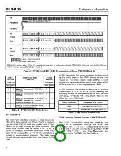
indicates that an input channel is bypassed to an output channel
ST-BUS/GCI Mode 3 supports connection to 2B+D devices where timeslots 0 and 1 transport D and C channels and echo canceller
(EC) I/O channels are assigned to ST-BUS timeslot 2 (B). Both PORT1 and PORT2 must be configured in Mode 3.
Figure 5 - ST-BUS and GCI 8-Bit Companded PCM I/O with D and C channels (Mode 3)
7

 MITEL [ MITEL NETWORKS CORPORATION ]