Preliminary Information
MT93L16
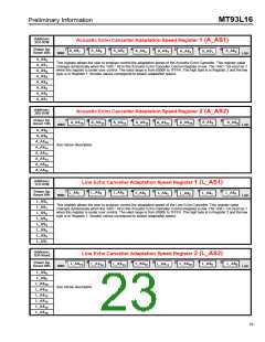
Address:
3Ch R/W
Acoustic Echo Canceller Adaptation Speed Register 1 (A_AS1)
7
6
5
4
3
2
1
0
Power Up
Reset 00h
A_AS
A_AS
5
A_AS
A_AS
A_AS
A_AS
A_AS
6
A_AS
2
7
4
0
3
1
MSB
LSB
A_AS
A_AS
A_AS
A_AS
A_AS
A_AS
A_AS
A_AS
0
1
2
3
4
5
6
7
This register allows the user to program control the adaptation speed of the Acoustic Echo Canceller. This register value
changes dynamically when the ’ASC-’ bit in the Acoustic Echo Canceller Control Register is low. The ’ASC-’ bit must be 1
when this register is under user control. The valid range is from 0000h to 7FFFh. The high byte is in Register 2 and the low
byte is in Register 1. Smaller values correspond to slower adaptation speed.
Address:
3Dh R/W
Acoustic Echo Canceller Adaptation Speed Register 2 (A_AS2)
Power Up
Reset 10h
7
6
5
4
3
2
1
0
A_AS
A_AS
A_AS
A_AS
A_AS
A_AS
A_AS
10
A_AS
9
8
12
15
14
13
11
MSB
LSB
A_AS
A_AS
8
9
A_AS
A_AS
A_AS
A_AS
A_AS
A_AS
10
11
12
13
14
15
See Above description
Address:
1Ch R/W
Line Echo Canceller Adaptation Speed Register 1 (L_AS1)
7
6
5
4
3
2
1
0
L_AS
Power Up
Reset 00h
L_AS
L_AS
5
L_AS
L_AS
L_AS
L_AS
6
L_AS
2
7
4
3
0
1
MSB
LSB
L_AS
L_AS
L_AS
L_AS
L_AS
L_AS
L_AS
L_AS
0
1
2
3
4
5
6
7
This register allows the user to program control the adaptation speed of the Line Echo Canceller. This register value
changes dynamically when the ’ASC-’ bit in the Acoustic Echo Canceller Control Register is low. The ’ASC-’ bit must be 1
when this register is under user control. The valid range is from 0000h to 7FFFh. The high byte is in Register 2 and the low
byte is in Register 1. Smaller values correspond to slower adaptation speed.
Address:
1Dh Read
Line Echo Canceller Adaptation Speed Register 2 (L_AS2)
7
6
5
4
3
2
1
0
Power Up
Reset 08h
L_AS
L_AS
8
L_AS
L_AS
L_AS
L_AS
L_AS
10
L_AS
9
12
15
14
13
11
MSB
LSB
L_AS
L_AS
8
9
L_AS
L_AS
L_AS
L_AS
L_AS
L_AS
10
11
12
13
14
15
See Above description
23

 MITEL [ MITEL NETWORKS CORPORATION ]