Advance Information
MT9300
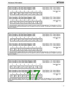
Echo Canceller A, Rin Peak Detect Register 2 (RP)
Echo Canceller B, Rin Peak Detect Register 2 (RP)
Read Address: 0Dh + Base Address
Read Address: 2Dh + Base Address
Power Reset Value
N/A
7
6
5
4
3
2
1
0
RP
RP
RP
RP
RP
RP
RP
RP
8
15
14
13
12
11
10
9
Echo Canceller A, Rin Peak Detect Register 1 (RP)
Echo Canceller B, Rin Peak Detect Register 1 (RP)
Read Address: 0Ch + Base Address
Read Address: 2Ch + Base Address
7
6
5
4
3
2
1
0
Power Reset Value
N/A
RP
RP
RP
RP
RP
RP
RP
RP
0
7
6
5
4
3
2
1
These peak detector registers allow the user to monitor the receive in signal (Rin) peak signal level. The information is in 16-bit 2’s
complement linear coded format presented in two 8 bit registers for each echo canceller. The high byte is in Register 2 and the low
byte is in Register 1.
Echo Canceller A, Sin Peak Detect Register 2 (SP)
Echo Canceller B, Sin Peak Detect Register 2 (SP)
Read Address: 0Fh + Base Address
Read Address: 2Fh + Base Address
7
6
5
4
3
2
1
0
Power Reset Value
N/A
SP
SP
SP
SP
SP
SP
SP
SP
8
15
14
13
12
11
10
9
Echo Canceller A, Sin Peak Detect Register 1 (SP)
Echo Canceller B, Sin Peak Detect Register 1 (SP)
Read Address: 0Eh + Base Address
Read Address: 2Eh + Base Address
7
6
5
4
3
2
1
0
Power Reset Value
N/A
SP
SP
SP
SP
SP
3
SP
SP
SP
0
7
6
5
4
2
1
These peak detector registers allow the user to monitor the send in signal (Sin) peak signal level. The information is in 16-bit 2’s
complement linear coded format presented in two 8 bit registers for each echo canceller. The high byte is in Register 2 and the low
byte is in Register 1.
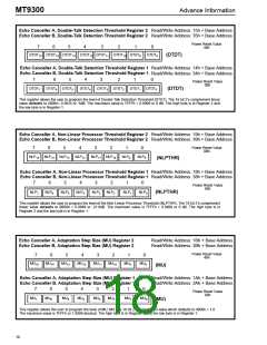
Echo Canceller A, Error Peak Detect Register 2 (EP)
Echo Canceller B, Error Peak Detect Register 2 (EP)
Read Address: 11h + Base Address
Read Address: 31h + Base Address
Power Reset Value
N/A
7
6
5
4
3
2
1
0
EP
EP
EP
EP
EP
EP
EP
EP
8
15
14
13
12
11
10
9
Echo Canceller A, Error Peak Detect Register 1 (EP)
Echo Canceller B, Error Peak Detect Register 1 (EP)
Read Address: 10h + Base Address
Read Address: 30h + Base Address
7
6
5
4
3
2
1
0
Power Reset Value
N/A
EP
EP
EP
EP
EP
3
EP
EP
EP
0
7
6
5
4
2
1
These peak detector registers allow the user to monitor the error signal peak level. The information is in 16-bit 2’s complement
linear coded format presented in two 8 bit registers for each echo canceller. The high byte is in Register 2 and the low byte is in
Register 1.
17

 MITEL [ MITEL NETWORKS CORPORATION ]