MT9300
Advance Information
Echo Canceller A, Flat Delay Register (FD)
Echo Canceller B, Flat Delay Register (FD)
Read/Write Address: 04h + Base Address
Read/Write Address: 24h + Base Address
7
6
5
4
3
2
1
0
FD
FD
FD
FD
FD
FD
FD
FD
0
7
6
5
4
3
2
1
Power Reset Value
00h
Echo Canceller A, Decay Step Number Register (NS)
Echo Canceller B, Decay Step Number Register (NS)
Read/Write Address: 07h + Base Address
Read/Write Address: 27h + Base Address
7
6
5
4
3
2
1
0
Power Reset Value
00h
NS
NS
NS
NS
NS
NS
NS
NS
0
7
6
5
4
3
2
1
Echo Canceller A, Decay Step Size Control Register (SSC)
Echo Canceller B, Decay Step Size Control Register (SSC)
Read/Write Address: 06h + Base Address
Read/Write Address: 26h + Base Address
7
6
5
4
3
2
1
0
0
0
0
0
0
SSC
SSC
SSC
0
2
1
Power Reset Value
04h
Note: Bits marked with “0” are reserved bits and should be written “0”.
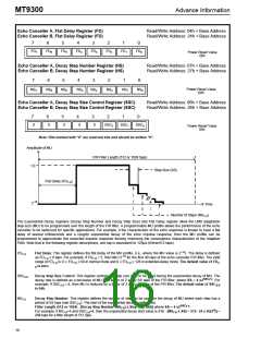
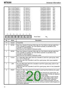
Amplitude of MU
FIR Filter Length (512 or 1024 taps)
1.0
Step Size (SS)
Flat Delay (FD
)
7-0
-16
2
Time
Number of Steps (NS
)
7-0
The Exponential Decay registers (Decay Step Number and Decay Step Size) and Flat Delay register allow the LMS adaptation
step-size (MU) to be programmed over the length of the FIR filter. A programmable MU profile allows the performance of the echo
canceller to be optimized for specific applications. For example, if the characteristic of the echo response is known to have a flat
delay of several milliseconds and a roughly exponential decay of the echo impulse response, then the MU profile can be
programmed to approximate this expected impulse response thereby improving the convergence characteristics of the Adaptive
Filter. Note that in the following register descriptions, one tap is equivalent to 125µs (64ms/512 taps).
-16
FD
Flat Delay: This register defines the flat delay of the MU profile, (i.e., where the MU value is 2 ). The delay is defined
7-0
-16
as FD
x 8 taps. For example; if FD = 5, then MU=2
for the first 40 taps of the echo canceller FIR filter. The valid
range of FD is: 0 ≤ FD ≤ 64 in normal mode and 0 ≤ FD ≤ 128 in extended-delay mode. The default value of FD
7-
7-0
7-0
7-0
7-0
7-0
is zero.
0
SSC
Decay Step Size Control: This register controls the step size (SS) to be used during the exponential decay of MU. The
decay rate is defined as a decrease of MU by a factor of 2 every SS taps of the FIR filter, where SS = 4 x2
2-0
SSC
2-0. For
example; If SSC = 4, then MU is reduced by a factor of 2 every 64 taps of the FIR filter. The default value of SSC
2-0
2-0
is 04h.
NS
Decay Step Number: This register defines the number of steps to be used for the decay of MU where each step has a
period of SS taps (see SSC ). The start of the exponential decay is defined as:
7-0
2-0
SSC
2-0
Filter Length (512 or 1024) - [Decay Step Number (NS ) x Step Size (SS)] where SS = 4 x2
.
7-0
4
For example, if NS =4 and SSC =4, then the exponential decay start value is 512 - [NS x SS] = 512 - [4 x (4x2 )] =
7-0
2-0
7-0
256 taps for a filter length of 512 taps.
16

 MITEL [ MITEL NETWORKS CORPORATION ]