Advance Information
MT9300
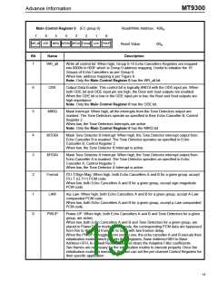
Main Control Register 0 (EC group 0)
Read/Write Address: 400
H
7
6
5
4
3
2
1
0
WR_all ODE
MIRQ MTDBI MTDAI Format LAW PWUP
Reset Value:
00 .
H
Bit
Name
Description
7
WR_all
Write all control bit: When high, Group 0-15 Echo Cancellers Registers are mapped
into 0000h to 003F which is Group 0 address mapping. Useful to initialize the 16
Groups of Echo Cancellers as per Group 0.
When low, address mapping is per Figure 8.
Note: Only the Main Control Register 0 has the WR_all bit.
6
5
ODE
Output Data Enable: This control bit is logically AND’d with the ODE input pin. When
both ODE bit and ODE input pin are high, the Rout and Sout outputs are enabled.
When the ODE bit is low or the ODE input pin is low, the Rout and Sout outputs are
high impedance.
Note: Only the Main Control Register 0 has the ODE bit.
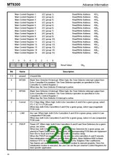
MIRQ
Mask Interrupt: When high, all the interrupts from the Tone Detectors output are
masked. The Tone Detectors operate as specified in their Echo Canceller B, Control
Register 2.
When low, the Tone Detectors Interrupts are active.
Note: Only the Main Control Register 0 has the MIRQ bit.
4
3
2
1
0
MTDBI
MTDAI
Format
LAW
Mask Tone Detector B Interrupt: When high, the Tone Detector interrupt output from
Echo Canceller B is masked. The Tone Detector operates as specified in Echo
Canceller B, Control Register 2.
When low, the Tone Detector B Interrupt is active.
Mask Tone Detector A Interrupt: When high, the Tone Detector interrupt output from
Echo Canceller A is masked. The Tone Detector operates as specified in Echo
Canceller A, Control Register 2.
When low, the Tone Detector A Interrupt is active.
ITU-T/Sign Mag: When high, both Echo Cancellers A and B for a given group, accept
ITU-T (G.711) PCM code.
When low, both Echo Cancellers A and B for a given group, accept sign-magnitude
PCM code.
A/µ Law: When high, both Echo Cancellers A and B for a given group, accept A-Law
companded PCM code.
When low, both Echo Cancellers A and B for a given group, accept µ-Law companded
PCM code.
PWUP
Power-UP: When high, both Echo Cancellers A and B and Tone Detectors for a given
group, are active.
When low, both Echo Cancellers A and B and Tone Detectors for a given group, are
placed in Power Down mode. In this mode, the corresponding PCM data are bypassed
from Rin to Rout and from Sin to Sout with two frames delay.
When the PWUP bit toggles from zero to one, the echo canceller A and B execute their
initialization routine which presets their registers, Base Address+00H to Base
Address+3FH, to default Reset Value and clears the Adaptive Filter coefficients.
Two frames are necessary for the initialization routine to execute properly. Once the
initialization routine is executed, the user can set the per channel Control Registers for
their specific application.
19

 MITEL [ MITEL NETWORKS CORPORATION ]