Advance Information
MT9160B/61B
Pin Description (continued)
Pin # Pin #
Name
Description
20 Pin 24 Pin
13
15
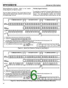
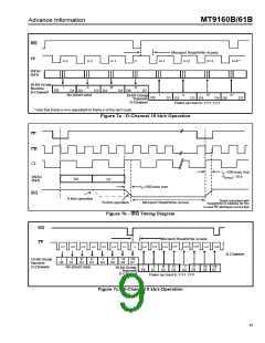
STB/F0i Data Strobe/Frame Pulse (Input). For SSI mode this input determines the 8 bit
timeslot used by the device for both transmit and receive data. This active high
signal has a repetition rate of 8 kHz. Standard frame pulse definitions apply in
ST-BUS mode (refer to figure 11). CMOS level compatible input.
16
STBd/ Delayed Frame Pulse Output. In SSI mode, an 8 bit wide strobe is output after the
(MT9161B
only)
FOod
first strobe goes low. In ST-BUS mode, a frame pulse is output 4 channel time slots
after /F0i.
14
17
CLOCKin Clock (Input). The clock provided to this input pin is used for the internal device
functions. For SSI mode connect the bit clock to this pin when it is 512 kHz or
greater. Connect a 4096 kHz clock to this input when the available bit clock is 128
kHz or 256 kHz. For ST-BUS mode connect C4i to this pin. CMOS level compatible.
15
16
17
18
19
20
V
Positive Power Supply (Input). Nominally 5 volts.
DD
HSPKR- Inverting Handset Speaker (Output). Output to the handset speaker (balanced).
HSPKR+ Non-Inverting Handset Speaker (Output). Output to the handset speaker
(balanced).
18
19
22
23
V
Analog Ground (Input). Nominally 0 volts.
SSA
M-
M+
NC
Inverting Microphone (Input). Inverting input to microphone amplifier from the
handset microphone.
20
24
Non-Inverting Microphone (Input). Non-inverting input to microphone amplifier
from the handset microphone.
3,9,
No Connect. (24 Pin Packages only). Pin 16 is NC for MT9160B.
16,21
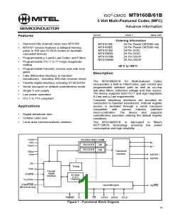
Overview
Functional Description
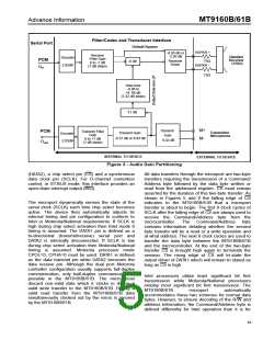
The 5V Multi-featured Codec (MFC) features
complete Analog/Digital and Digital/Analog
Filter/Codec
conversion of audio signals (Filter/Codec) and an
analog interface to a standard handset transmitter
and receiver (Transducer Interface). The receiver
amplifier is capable of driving a 300 ohm load.
The Filter/Codec block implements conversion of the
analog 0-3.3 kHz speech signals to/from the digital
domain compatible with 64 kb/s PCM B-Channels.
Selection of companding curves and digital code
assignment are programmable. These are ITU-T
G.711 A-law or µ-Law, with true-sign/Alternate Digit
Inversion or true-sign/Inverted Magnitude coding,
respectively. Optionally, sign-magnitude coding may
also be selected for proprietary applications.
Each of the programmable parameters within the
functional blocks is accessed through a serial
®
microcontroller port compatible with Intel MCS-51 ,
®
Motorola SPI
Microwire
and National Semiconductor
These parameters
®
specifications.
include: gain control, power down, mute, B-Channel
select (ST-BUS mode), C&D channel control/access,
law control, digital interface programming and
loopback. Optionally the device may be used in a
controllerless mode utilizing the power-on default
settings.
The Filter/Codec block also implements transmit and
receive audio path gains in the analog domain. A
programmable gain, voice side-tone path is also
included to provide proportional transmit speech
feedback to the handset receiver. This side tone path
feature is disabled by default. Figure 3 depicts the
nominal half-channel and side-tone gains for the
MT9160B/61B.
81

 MITEL [ MITEL NETWORKS CORPORATION ]