MT9079
through bit 6 of the per time slot control words (pages
7 and 8).
signal to the far end of the link. This transmission will
cease when signalling multiframe alignment is
acquired.
c) DWM7-0 - Detect Word Mask 7 to 0 (page 1,
address 19H) is an eight bit code, which determines
the bits that will be considered in the comparison
between the receive data and the Code Detect Word
(CDW7-0). If one, the bit position will be included - if
zero, the bit position will be excluded.
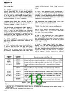
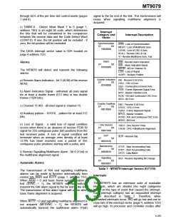
Interrupt
Category and
Vector
Interrupt Description
Synchronization
SYNI - Loss of Synchronization.
MFSYI - Loss of Multiframe Sync.
CSYNI - Loss of CRC-4 Sync.
RFALI - Remote CRC-4 Fail.
D7
D0
10000000
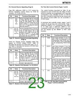
The DATA interrupt vector value is 02H located on
page 4 address 12H.
YI - Remote Multiframe Sync. Fail.
Alarm
RAII - Remote Alarm Indication.
AISI - Alarm Indication Signal.
AIS16I - AIS on Channel 16.
LOSI - Loss of Signal.
Alarms
D7
D0
01000000
The MT9079 will detect and transmit the following
alarms:
AUXPI - Auxiliary Pattern.
Counter Indication
D7 D0
00100000
EBI - Receive E-bit Error.
a) Remote Alarm Indication - bit 3 (ALM) of the receive
NFAS;
CRCI - CRC-4 Error.
CEFI - Consecutive Errored FASs.
FERI - Frame Alignment Signal Error.
BPVI - Bipolar Violation Error.
RCRI - RAI and Continuous CRC Error.
BERI - Bit Error.
b) Alarm Indication Signal - unframed all ones signal
for at least a double frame (512 bits) or two double
frames (1024 bits);
Counter Overflow
D7 D0
00010000
EBO - Receive E-bit Error.
CRCO - CRC-4 Error.
c) Channel 16 AIS - all ones signal in channel 16;
FERO - Frame Alignment Signal.
BPVO - Bipolar Violation.
RCRO - RAI and Continuous CRC Error.
BERO - Bit Error
d) Auxiliary pattern - 101010... pattern for at least 512
bits;
e) Loss of Signal - a valid loss of signal condition
occurs when there is an absence of receive PCM 30
signal for 255 contiguous pulse (bit) positions from the
last received pulse. A loss of signal condition will
terminate when an average ones density of at least
12.5% has been received over a period of 255
contiguous pulse positions starting with a pulse; and
One Second
D7 D0
1SECI - One Second Timer.
CALNI - CRC-4 Multiframe Alignment.
00001000
SLIP
SLPI - Receive Slip.
D7
D0
00000100
Maintenance
D7 D0
STOP - Stop Accumulating Data.
STRT - Start Accumulating Data.
DATA - Data Match.
00000010
f) Remote Signalling Multiframe Alarm - bit 6 (Y-bit) of
the multiframe alignment signal.
Signalling
00000001
SIGI - Receive Signalling Bit Change.
D7
D0
Automatic Alarms
Table 7 - MT9079 Interrupt Vectors (IV7-IV0)
Interrupts
The transmission of RAI and signalling multiframe
alarms can be made to function automatically from
control bits ARAI and AUTY (page 1, address 11H).
When ARAI = 0 and basic frame synchronization is
lost (SYNC = 1), the MT9079 will automatically
transmit the RAI alarm signal to the far end of the link.
The transmission of this alarm signal will cease when
basic frame alignment is acquired.
The MT9079 has an extensive suite of maskable
interrupts, which are divided into eight categories
based on the type of event that caused the interrupt.
Each interrupt category has an associated interrupt
vector described in Table 7. Therefore, when
unmasked interrupts occur, IRQ will go low and one or
more bits of the interrupt vector (page 4, address 12H)
will go high. In processor and controller modes after
When AUTY = 0 and signalling multiframe alignment is
not acquired (MFSYNC = 1), the MT9079 will
automatically transmit the multiframe alarm (Y-bit)
4-255

 MITEL [ MITEL NETWORKS CORPORATION ]