MT9076
Preliminary Information
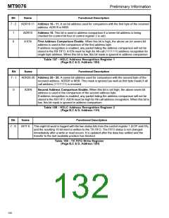
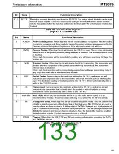
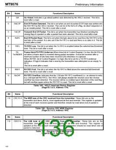
Bit
Name
Functional Description
7
GA
Go Ahead. Indicates a go-ahead pattern was detected by the HDLC receiver. This bit is
reset after a read.
6
RxEOP
End Of Packet Detected. This bit is set when an end of packet (EOP) byte was written into
the RX FIFO by the HDLC receiver. This can be in the form of a flag, an abort sequence or
as an invalid packet. This bit is reset after a read.
5
4
TxEOP
RxFE
Transmit End Of Packet. This bit is set when the transmitter has finished sending the
closing flag of a packet or after a packet has been aborted. This bit is reset after read.
End Of Packet Read. This bit is set when the byte about to be read from the RX FIFO is the
last byte of the packet. It is also set if the Rx FIFO is read and there is no data in it. This bit
is reset after a read.
3
2
TXFL
FA:
TX FIFO Low. This bit is set when the Tx FIFO is emptied below the selected low threshold
level. This bit is reset after a read.
Frame Abort/TX FIFO Underrun.When Intsel bit of Control Register 2 is low, this bit (FA) is
TxUNDER set when a frame abort is received during packet reception. It must be received after a
minimum number of bits have been received (26) otherwise it is ignored.
When INTSEL bit of Control Register 2 is high, this bit is set for a TX FIFO underrun
indication. If high it Indicates that a read by the transmitter was attempted on an empty Tx
FIFO.
This bit is reset after a read.
1
0
RXFF
RX FIFO Full. This bit is set when the Rx FIFO is filled above the selected full threshold
level. This bit is reset after a read.
RxOVF
RX FIFO Overflow. Indicates that the 128 byte RX FIFO overflowed (i.e. an attempt to write
to a 128 byte full RX FIFO). The HDLC will always disable the receiver once the receive
overflow has been detected. The receiver will be re-enabled upon detection of the next flag,
but will overflow again unless the RX FIFO is read. This bit is reset after a read.
Table 165 - HDLC Interrupt Status Register
(Page B,C & D, Address 17H)
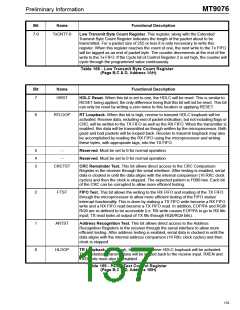
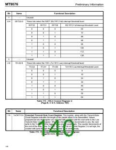
Bit
Name
Functional Description
7-0
CRC15-8 The MSB byte of the CRC received from the transmitter. These bits are as the
transmitter sent them; that is, most significant bit first and inverted. This register is updated
at the end of each received packet and therefore should be read when end of packet is
detected.
Table 166 - Receive CRC MSB Register
(Page B,C & D, Address 18H)
Bit
Name
Functional Description
7-0
CRC7-0 The LSB byte of the CRC received from the transmitter. These bits are as the
transmitter sent them; that is, most significant bit first and inverted. This register is
updated at the end of each received packet and therefore should be read when end of
packet is detected.
Table 167 - Receive CRC LSB Register
(Page B,C & D, Address 19H)
132

 MITEL [ MITEL NETWORKS CORPORATION ]