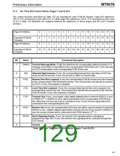
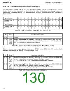
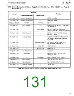
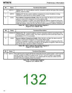
Preliminary Information
MT9076
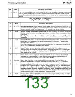
Bit
Name
Functional Description
7 - 0
BIT7-0 This is the received data byte read from the RX FIFO. The status bits of this byte can be read
from the status register. The FIFO status is not changed immediately when a write or read
occurs. It is updated after the data has settled and the transfer to the last available position has
finished.
Table 160 - RX FIFO Read Register
(Page B,C & D, Address 12H)
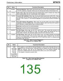
Bit
Name
Functional Description
7
ADREC
Address Recognition. When high this bit will enable address recognition. This forces the
receiver to recognize only those packets having the unique address as programmed in the
Receive Address Recognition Registers or if the address is an All call address.
6
5
RxEN
TxEN
Receive Enable. When low this bit will disable the HDLC receiver. The receiver will disable
after the rest of the packet presently being received is finished. The receiver internal clock
is disabled.
When high the receiver will be immediately enabled and will begin searching for flags, Go-
aheads etc.
Transmit Enable. When low this bit will disable the HDLC transmitter. The transmitter will
disable after the completion of the packet presently being transmitted. The transmitter
internal clock is disabled.
When high the transmitter will be immediately enabled and will begin transmitting data, if
any, or go to a mark idle or interframe time fill state.
4
3
EOP
FA
End of Packet. Forms a tag on the next byte written the TX FIFO, and when set will
indicate an end of packet byte to the transmitter, which will transmit an FCS following this
byte. This facilitates loading of multiple packets into TX FIFO. Reset automatically after a
write to the TX FIFO occurs.
Frame Abort. Forms a tag on the next byte written to the TX FIFO, and when set will
indicate to the transmitter that it should abort the packet in which that byte is being
transmitted. Reset automatically after a write to the TX FIFO.
2
1
Mark-Idle Mark - Idle. When low, the transmitter will be in an idle state. When high it is in an
interframe time fill state. These two states will only occur when the TX FIFO is empty.
TR
Transparent Mode. When high this bit will enable transparent mode. This will perform the
parallel to serial conversion without inserting or deleting zeros. No CRC bytes are sent or
monitored nor are flags or aborts. A falling edge of TxEN for transmit and a falling edge of
RxEN for receive is necessary to initialize transparent mode. This will also synchronize the
data to the transmit and receive channel structure. Also, the transmitter must be enabled
through control register 1 before transparent mode is entered.
0
FRUN
Freerun. When high the HDLC TX and RX are continuously enabled providing the RxEN
and TxEN bits are set.
Table 161 - HDLC Control Register 1
(Page B,C & D, Address 13H)
129

 MITEL [ MITEL NETWORKS CORPORATION ]