MT9076
Preliminary Information
Word, page 1H, address 10H), multiframe alignment is forced at the same time as terminal frame alignment. If
only Ft bits are checked, multiframe alignment is forced separately, upon detection of the Fs bit history of
00111 (for normal D4 trunks) or 000111000111 (for SLC-96 trunks). For D4 trunks, a reframe on the multiframe
alignment may be forced at any time without affecting terminal frame alignment.
In ESF mode, the circuit will optionally confirm the CRC-6 bits before forcing a new frame alignment. This is
programmed by setting control bit CXC high (bit 5 of the Framing Mode Select Word, page 1H, address 10H). A
CRC-6 confirmation adds a minimum of 6 milliseconds to the reframe time. If no CRC-6 match is found after 16
attempts, the framer moves to the next valid candidate bit position (assuming other bit positions contain a
match to the framing pattern) or re-initiates the whole framing procedure (assuming no bit positions have been
found to match the framing pattern).
The framing circuit is off - line. During a reframe, the rest of the circuit operates synchronous with the last frame
alignment. Until such time as a new frame alignment is achieved, the signaling bits are frozen in their states at
the time that frame alignment was lost, and error counting for Ft, Fs, ESF framing pattern or CRC-6 bits is
suspended.
10.2
Frame Alignment in E1 mode
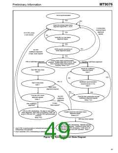
In E1 mode, MT9076 contains three distinct framing algorithms: basic frame alignment, signaling multiframe
alignment and CRC-4 multiframe alignment. Figure 16 is a state diagram that illustrates these algorithms and
how they interact.
After power-up, the basic frame alignment framer will search for a frame alignment signal (FAS) in the PCM 30
receive bit stream. Once the FAS is detected, the corresponding bit 2 of the non-frame alignment signal (NFAS)
is checked. If bit 2 of the NFAS is zero a new search for basic frame alignment is initiated. If bit 2 of the NFAS
is one and the next FAS is correct, the algorithm declares that basic frame synchronization has been found
(i.e., page 03H, address 10H, bit 7, SYNC is zero).
Once basic frame alignment is acquired the signaling and CRC-4 multiframe searches will be initiated. The
signaling multiframe algorithm will align to the first multiframe alignment signal pattern (MFAS = 0000) it
receives in the most significant nibble of channel 16 (page 3, address 10H, bit 6, MFSYNC = 0). signaling
multiframing will be lost when two consecutive multiframes are received in error.
The CRC-4 multiframe alignment signal is a 001011 bit sequence that appears in PCM 30 bit position one of
the NFAS in frames 1, 3, 5, 7, 9 and 11 (see Table 11). In order to achieve CRC-4 synchronization two
consecutive CRC-4 multiframe alignment signals must be received without error (page 03H, address 10H
CRCSYN = 0).
The E1 framing algorithm supports automatic interworking of interfaces with and without CRC-4 processing
capabilities. That is, if an interface with CRC-4 capability, achieves valid basic frame alignment, but does not
achieve CRC-4 multiframe alignment by the end of a predefined period, the distant end is considered to be a
non-CRC-4 interface. When the distant end is a non-CRC-4 interface, the near end automatically suspends
receive CRC-4 functions, continues to transmit CRC-4 data to the distant end with its E-bits set to zero, and
provides a status indication. Naturally, if the distant end initially achieves CRC-4 synchronization, CRC-4
processing will be carried out by both ends. This feature is selected when control bit AUTC (page 01H, address
10H) is set to zero.
44

 MITEL [ MITEL NETWORKS CORPORATION ]