MT9076
Preliminary Information
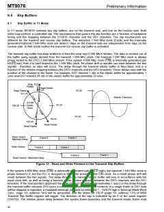
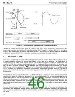
0 uS
Write
Pointer
Read Pointer
4 uS
92 uS
Read Pointer
221 uS
Wander Tolerance
512 Bit
Elastic
Store
62 uS
188 uS
92 uS
96 uS
Read Pointer
129 uS
Read Pointer
Read Vectors
Minimum Delay
Frame 0
Frame 1
Write Vectors
Frame 0
Frame 1
Frame 1
Frame 0
Read Vectors - Maximum Delay
Figure 13 - Read and Write Pointers in the Transmit Slip Buffers
The RSLIP and RSLPD status bits (page 3H, address 13H, bits 7 and 6 respectively) give indication of a
receive slip occurance and direction. A maskable interrupt RxSLPI (page 1H, address 1BH, bit 0 - set high to
mask) is also provided. RSLIP changes state in the event of a slip. If RSLPD=0, the slip buffer has overflowed
and a frame was lost; if RSLPD=1, a underflow condition occurred and a frame was repeated.
9.2
Slip Buffer in E1 mode
In E1 mode, in addition to the elastic buffer in the jitter attenuator(JA), another elastic buffer (two frames deep)
is present, attached between the receive side and the ST-BUS side of the MT9076. This elastic buffer is
configured as a slip buffer which absorbs wander and low frequency jitter in multi-trunk applications. The
received PCM 30 data is clocked into the slip buffer with the Exclk clock and is clocked out of the slip buffer with
the C4b clock. The Exclk extracted clock is generated from, and is therefore phase-locked with, the receive
PCM 30 data. In normal operation, the C4b clock will be phase-locked to the Exclk clock by a phase locked loop
(PLL). Therefore, in a single trunk system the receive data is in phase with the Exclk clock, the C4b clock is
phase-locked to the Exclk clock, and the read and write positions of the slip buffer will remain fixed with respect
to each other.
In a multi-trunk slave or loop-timed system (i.e., PABX application) a single trunk will be chosen as a network
synchronizer, which will function as described in the previous paragraph. The remaining trunks will use the
system timing derived from the synchronizer to clock data out of their slip buffers. Even though the PCM 30
signals from the network are synchronous to each other, due to multiplexing, transmission impairments and
route diversity, these signals may jitter or wander with respect to the synchronizing trunk signal. Therefore, the
Exclk clocks of non-synchronizer trunks may wander with respect to the Exclk clock of the synchronizer and the
system bus.
Network standards state that, within limits, trunk interfaces must be able to receive error-free data in the
presence of jitter and wander (refer to network requirements for jitter and wander tolerance). The MT9076 will
allow a maximum of 26 channels (208 UI, unit intervals) of wander and low frequency jitter before a frame slip
will occur.
42

 MITEL [ MITEL NETWORKS CORPORATION ]