MT90732 CMOS
Advance Information
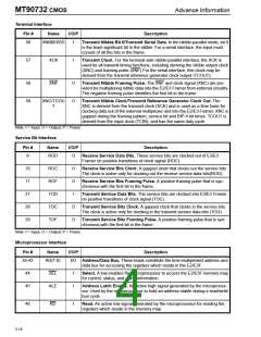
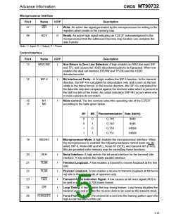
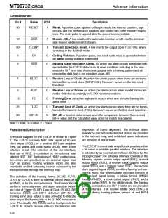
Control Interface
Pin #
Name
I/O/P
Description
30
RESET
I
Reset. A positive pulse applied to this pin resets the internal counters, logic
circuits, and the performance counters and control bits in the memory map to
zero. The reset pulse is applied after the power becomes stable.
49
50
5
DAIS
TLCINV
CV
I
Disable AIS. A low disables the automatic insertion of AIS into the terminal
side receive nibble/serial bit stream.
I
Transmit Line Clock Invert. A low inverts the output clock TCK/TCKL when
operating in the dual rail mode.
O
O
Coding Violation. A positive pulse, one clock cycle wide, is generated when
an illegal coding violation is detected.
6
RAIS
Receive Alarm Indication Signal. An active low alarm occurs within one milli-
second after the E2/E3F detects an all ones condition, including in the pres-
-3
ence of a 10 error rate. An incoming signal with a framing pattern and all
ones in the data field is not mistaken as an AIS.
7
RLOC
O
Receive Loss of Clock. An active low alarm occurs when there are no transi-
tions in the received clock (RCK/RCKL). Recovery occurs on the first clock
transition.
RLOF
FE
8
O
O
O
O
Receive Loss of Frame. An active low alarm occurs when a valid frame can-
not be detected accordingly to G.7XX recommendations.
12
25
60
Framing Error. An active high alarm occurs when one or more framing bits
are in error.
TLOC
BIP-4E
Transmit Loss of Clock. An active low alarm occurs when there are no transi-
tions in the transmit clock (TCK). Recovery occurs on the first clock transition.
BIP-4E. A positive pulse occurs when the comparison between the received
BIP-4 value and the calculated value does not match in a column.
Note: I = Input, O = Output, P = Power
regardless of frame alignment. The external alarm
indications (latched and unlatched states) are provided
Functional Description
in the memory map, and unlatched alarm indications
are provided at signal leads.
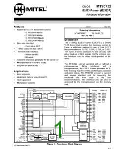
The block diagram for the E2/E3F is shown in Figure
1. The E2/E3F receives NRZ data signal (RDL) and
clock signal (RCKL), or a positive (RP) and negative
(RN) rail signal and clock signal (RCK), from a line
interface circuit. The selection of the line interface,
dual rail or NRZ, is controlled by the external lead
labeled NRZ LINE. Indications of HDB3 coding viola-
tion errors are provided on an external signal lead
(CV) as pulses. Coding violation errors are also
counted in an 8-bit saturating counter accessed by the
microprocessor through the memory map.
The E2/E3F terminal side output block provides either
a bit-serial or a nibble-parallel interface. The interface
is selected by an external control lead (SER) or by the
microprocessor. The bit-serial interface consists of the
following signals: a data output signal (RSD), a clock
output signal (RSC), a receive clock gapped output
signal (RCG), and a framing pulse (RSF). The receive
clock gapped signal (RCG) identifies framing and ser-
vice bit times. The nibble-parallel interface consists of
data output signal having a nibble format (RNIB3
through RNIB0), a clock output signal (RNC), and a
framing pulse (RNF). In the nibble mode, the framing
pattern, service bits and BIP-4 nibble are not provided
at the interface. The receive nibble clock (RNC) is
gapped during framing pattern, service bit and BIP-4
times.
The selection of the framing format (G.742, G.745,
G.751 or G.753) is done by external control leads (M1
and M0), or by the microprocessor. The Framer Block
performs frame alignment and alarm detection includ-
ing Loss of Frame (RLOF), Loss of Clock (RLOC), AIS
detection (RAIS) and BIP-4 detection (BIP-4E). A
framing error (FE) output is also provided to indicate
when any of the framing bits in the G. 7XX frame are in
error. The disable AIS (DAIS) control lead permits the
E2/E3F to provide receive data on the terminal side
5-20

 MITEL [ MITEL NETWORKS CORPORATION ]