MT9041B
Advance Information
For the MT9041B, two internal elements determine
the jitter attenuation. This includes the internal 1.9Hz
low pass loop filter and the phase slope limiter. The
phase slope limiter limits the output phase slope to
5ns/125us. Therefore, if the input signal exceeds this
rate, such as for very large amplitude low frequency
input jitter, the maximum output phase slope will be
limited (i.e., attenuated) to 5ns/125us.
usually made with large input jitter signals (e.g. 75%
of the specified maximum jitter tolerance).
Frequency Accuracy
Frequency accuracy is defined as the absolute
tolerance of an output clock signal when it is not
locked to an external reference, but is operating in a
free running mode. For the MT9041B, the Freerun
accuracy is equal to the Master Clock (OSCi)
accuracy.
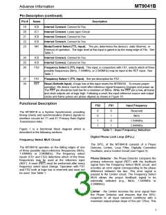
The MT9041B has nine outputs with three possible
input frequencies for a total of 27 possible jitter
transfer functions. However, the data sheet section
on AC Electrical Characteristics - Jitter Transfer
specifies transfer values for only three cases, 8kHz
to 8kHz, 1.544MHz to 1.544MHz and 2.048MHz to
2.048MHz. Since all outputs are derived from the
same signal, these transfer values apply to all
outputs.
Capture Range
Also referred to as pull-in range. This is the input
frequency range over which the synchronizer must
be able to pull into synchronization. The MT9041B
capture range is equal to ±230ppm minus the
accuracy of the master clock (OSCi). For example, a
±32ppm master clock results in a capture range of
±198ppm.
It should be noted that 1UI at 1.544MHz is 644ns,
which is not equal to 1UI at 2.048MHz, which is
488ns. Consequently, a transfer value using different
input and output frequencies must be calculated in
common units (e.g. seconds) as shown in the
following example.
Lock Range
This is the input frequency range over which the
synchronizer
must
be
able
to
maintain
What is the T1 and E1 output jitter when the T1 input
jitter is 20UI (T1 UI Units) and the T1 to T1 jitter
attenuation is 18dB?
synchronization. The lock range is equal to the
capture range for the MT9041B.
–A
------
20
Phase Slope
OutputT1 = InputT1×10
Phase slope is measured in seconds per second and
is the rate at which a given signal changes phase
with respect to an ideal signal. The given signal is
typically the output signal. The ideal signal is of
constant frequency and is nominally equal to the
value of the final output signal or final input signal.
–18
--------
20
OutputT1 = 20×10
= 2.5UI(T1)
(1UIT1)
---------------------
(1UIE1)
OutputE1 = OutputT1 ×
(644ns)
(488ns)
-------------------
OutputE1 = OutputT1 ×
= 3.3UI(T1)
Phase Continuity
Using the above method, the jitter attenuation can be
calculated for all combinations of inputs and outputs
based on the three jitter transfer functions provided.
Phase continuity is the phase difference between a
given timing signal and an ideal timing signal at the
end of a particular observation period. Usually, the
given timing signal and the ideal timing signal are of
the same frequency. Phase continuity applies to the
output of the synchronizer after a signal disturbance
due to a reference switch or a mode change. The
observation period is usually the time from the
disturbance, to just after the synchronizer has settled
to a steady state.
Note that the resulting jitter transfer functions for all
combinations of inputs (8kHz, 1.544MHz, 2.048MHz)
and
outputs
(8kHz,
1.544MHz,
2.048MHz,
4.096MHz, 8.192MHz, 16.384MHz) for a given input
signal (jitter frequency and jitter amplitude) are the
same.
Since intrinsic jitter is always present, jitter
attenuation will appear to be lower for small input
jitter signals than for large ones. Consequently,
accurate jitter transfer function measurements are
In the case of the MT9041B, the output signal phase
continuity is maintained to within ±5ns at the
instance (over one frame) of mode changes. The
total phase shift may accumulate up to ±200ns over
6

 MITEL [ MITEL NETWORKS CORPORATION ]