ISO-CMOS MT8952B
Idle state:
The serial port can be configured to operate in two
modes depending on the IC bit in the Timing Control
Register. It can transmit/receive the packets on
selected timeslots in ST- BUS format or it can,
using the enable signals (TxCEN and RxCEN),
transmit/receive the packets at a bit rate equal to CKi
clock input.
The Idle state is defined as 15 or more contiguous
ONEs. When the HDLC Protocol Controller is
observing this condition on the receiving channel,
the Idle bit in the General Status Register is set
HIGH. On the transmit side, the Protocol Controller
ends the Idle state when data is loaded into the
transmit FIFO.
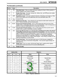
The microprocessor port allows parallel data
transfers between the Protocol Controller and a
6800/6809 system bus. This interface consists of
Data Bus (D0-D7), Address Bus (A0-A3), E Clock,
Chip Select (CS) and R/W control. The micro-
processor can read and write to the various registers
in the Protocol Controller. The addresses of these
registers are given in Table 2. The IRQ is an open
drain, active LOW output indicating an interrupt
request to CPU. Control and monitoring of many
different interrupts that may originate from the
protocol controller is implemented by the Interrupt
Flag Register (IFR) and the Interrupt Enable
Register (IER). Specific events have been described
that set a bit HIGH in the Interrupt Flag Register.
Such an event does not necessarily interrupt the
CPU. To assert an interrupt (pull IRQ output LOW)
the bit in IER that coincides with the Interrupt Flag
Register must be set HIGH. The IRQ bit in the
General Status Register is the complement of IRQ
pin status. If an interrupt is asserted, this bit will be
set HIGH otherwise it will be LOW.
Interframe time fill state:
The Protocol Controller transmits continuous flags
(7E ) in Interframe time fill state and ends this
Hex
state when data is loaded into the transmit FIFO.
Go Ahead state:
Go Ahead is defined by the 9 bit sequence
011111110 (7F
followed by a ZERO), and hence
Hex
contiguous 7F’s appear as Go Aheads. Once the
transmitter is in ‘Go Ahead’ state, it will continue to
remain so even after the data is loaded into the
FIFO. This state can only be changed by setting the
IFTF bits in the Control Register to something other
than ‘GO Ahead’. The reception of this sequence is
indicated by GA bit in the General Status Register
and the Protocol Controller can generate an interrupt
if enabled to do so by the GA bit in the Interrupt
Enable Register.
TEOP and REOP Outputs:
Transparent Data Transfer State:
The HDLC Protocol Controller provides two separate
signals TEOP & REOP indicating the end of packet
transmitted and received respectively. TEOP is a
HIGH going pulse for one bit duration asserted
during the last bit of the closing flag or Abort
sequence of the transmit packet. REOP is also a
HIGH going pulse occurring for one bit period when
a closing flag is received or an incoming packet is
aborted or an invalid packet of 24 or more bits is
detected. However, REOP is not generated for
invalid packets of length less than 24 bits. These
‘end of packet’ signals are useful in multiplexing
several data links on to a single HDLC Protocol
Controller.
The Protocol Controller, in this state, disables the
protocol functions defined earlier and provides bi-
directional access to the serial bit streams through
the parallel port. Like other states, the transparent
data transfer can be selected in both timing modes.
Invalid Frames
Any frame shorter than 32 bits between the opening
and closing flags (corresponding to 16 bits of data
and 16 bits FCS) is considered invalid. The Protocol
Controller ignores the frame only if the frame length
is less than 24 bits between the flags. For frames of
length 24 to 32 bits, it transfers the data field to FIFO
and tags it as having bad FCS in the FIFO Status
Register.
Timing Modes
There are two timing modes the Protocol Controller
can be run in. These timing modes refer only to the
configuration of the serial port and are not related to
the microprocessor port.
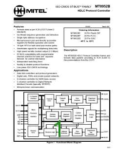
Functional Description
The functional block diagram of the HDLC Protocol
Controller is shown in Figure 1. It has two ports.
The serial port transmits and receives formatted data
Internal Timing Mode
packets and the parallel port provides
a
microprocessor interface for access to various
registers in the Protocol Controller.
The Internal Timing Mode is intended for an easy
interface to various products using ST-BUS
3-65

 MITEL [ MITEL NETWORKS CORPORATION ]