MT8952B ISO-CMOS
1
2
VDD
RST
F0i
CKi
TEOP
REOP
D7
D6
D5
D4
D3
28
27
26
25
24
23
22
21
20
19
18
17
TxCEN
RxCEN
CDSTo
CDSTi
WD
3
4
5
6
7
•
CKi
TEOP
REOP
D7
WD
5
25
24
23
22
21
20
19
6
IRQ
A0
A1
A2
A3
IRQ
A0
A1
A2
A3
CS
E
R/W
VSS
7
8
8
9
9
D6
10
11
D5
D4
CS
10
11
12
13
14
D2
D1
D0
16
15
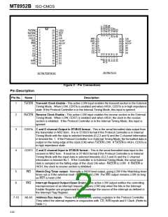
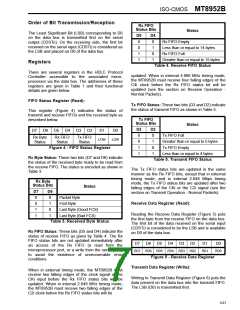
28 PIN PLCC
28 PIN PDIP/SOIC
Figure 2 - Pin Connections
Description
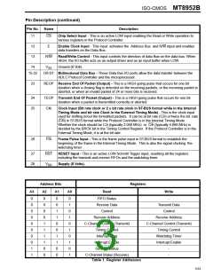
Pin Description
Pin No.
Name
1
TxCEN Transmit Clock Enable - This active LOW input enables the transmit section in the External
Timing Mode. When LOW, CDSTo is enabled and when HIGH, CDSTo is in high impedance
state. If the Protocol Controller is in the Internal Timing Mode, this input is ignored.
2
3
RxCEN Receive Clock Enable - This active LOW input enables the receive section in the External
Timing Mode. When LOW, CDSTi is enabled and when HIGH, the clock to the receive
section is inhibited. If the Protocol Controller is in the Internal Timing Mode, this input is
ignored.
CDSTo C and D channel Output in ST-BUS format - This is the serial formatted data output from
the transmitter in NRZ form. It is in ST-BUS format if the Protocol Controller is in Internal
Timing Mode with the data in selected timeslots (0,2,3 and 4) and the C-channel information
in timeslot No. 1. If the Protocol Controller is in External Timing Mode, the formatted data is
output on the rising edge of the clock (CKi) when TxCEN LOW. If TxCEN is HIGH, CDSTo is
in high impedance state.
4
CDSTi C and D channel Input in ST-BUS format - This is the serial formatted data input to the
receiver in NRZ form. It must be in ST-BUS format if the Protocol Controller is in Internal
Timing Mode with the input data in selected timeslots (0,2,3 and 4) and the C-channel
information in timeslot No.1. If the Controller is in External Timing Mode, the serial input
data is sampled on the falling edge of the clock CKi when RxCEN is LOW. If RxCEN is
HIGH, the clock to receive section is inhibited.
5
6
WD
Watch-Dog Timer output - Normally a HIGH level output, going LOW if the Watchdog timer
times out or if the external reset (RST) is held LOW. The WD output remains LOW as long
as RST is held LOW.
IRQ
Interrupt Request Output (Open Drain) - This active LOW output notifies the controlling
microprocessor of an interrupt request. It goes LOW only when the bits in the Interrupt
Enable Register are programmed to acknowledge the source of the interrupt as defined in
the Interrupt Flag Register.
7-10
A0-A3 Address Bus Inputs - These bits address the various registers in the Protocol Controller.
They select the internal registers in conjunction with CS, R/W inputs and E Clock. (Refer to
Table 1.)
3-62

 MITEL [ MITEL NETWORKS CORPORATION ]