Preliminary Information
MH89760B
allows the device to interface with systems that have
already applied some form of zero code suppression
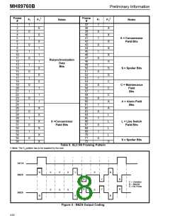
to the data input on DSTi. B8ZS zero code
suppression replaces all strings of 8 zeros with a
known bit pattern and a specific pattern of bipolar
violations. This bit pattern and violation pattern is
shown in Figure 4. The receiver monitors the
received bit pattern and the bipolar violation pattern
and replaces all matching strings with 8 zeros.
The MH89760B also has a per channel loopback
mode. See Table 6 and the following section for more
information.
Per Channel Control Features
In addition to the two master control words in CSTi0
there are also 24 Per Channel Control Words. These
control words only affect individual DS0 channels.
The correspondence between the channels on
CSTi0 and the affected DS0 channel is shown in Fig.
3. Each control word has three bits that enable
robbed bit signalling, DS0 channel loopback and
inversion of the DS0 channel. A full description of
each of the bits is provided in Table 6.
Loopback Modes
Remote and digital loopback modes are enabled by
bits 6 and 7 in Master Control Word 2. These modes
can be used for diagnostics in locating the source of
a fault condition. Remote loop around loops back
data received at RxR and RxT back out on OUTA
and OUTB, thus effectively sending the received
DS1 data back to the far end unaltered so that the
transmission line can be tested. The received signal
with the appropriate received channels on the DS1
side made available in the proper format at DSTo.
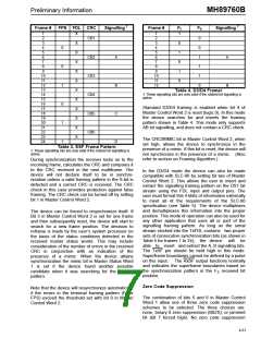
Transmit Signalling Bits
Control ST-BUS input number 1 (CSTi1) contains 24
additional per channel control words. These 24 ST-
BUS channels contain the A, B, C and D signalling
bits that the device uses at transmit time. The
position of these 24 per channel control words in the
ST-BUS is shown in Figure 3 and the position of the
ABCD signalling bits is shown in Table 7. Even
though the device only inserts the signalling
information in every 6th DS1 frame this information
must be input every ST-BUS frame.
The digital loop around mode diverts the data
received at DSTi back out the DSTo pin. Data
received on DSTi is, however, still transmitted out via
OUTA and OUTB. This loop back mode can be used
to test the near end interface equipment when there
is no transmission line or when there is a suspected
failure of the line.
Robbed bit signalling can be disabled for all
channels on the DS1 link by bit 1 of Master Control
Word 1. It can also be disabled on a per channel
basis by bit 0 in the Per Channel Control Word 1.
The all ones transmit alarm (also known as the blue
alarm or the keep alive signal) can be activated in
conjunction with the digital loop around so that the
transmission line sends an all 1's signal while the
normal data is looped back locally.
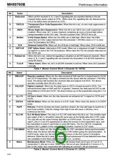
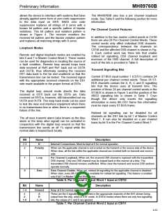
Bit
Name
Description
7-3
2
IC
Internal Connections. Must be kept at 0 for normal operation.
Polarity
When set, the applicable channel is not inverted on the transmit or the receive side of the device.
When clear, all the bits within the applicable channel are inverted both on transmit and receive
side.
1
0
Loop
Data
Per Channel Loopback. When set, the received DS0 channel is replaced with the transmitted
DS0 channel. Only one DS0 channel may be looped back in this manner at a time. The
transmitted DS0 channel remains unaffected. When clear the transmit and receive DS0 sections
operate normally.
Data Channel Enable. When set, robbed bit signalling for the applicable channel is disabled.
When clear, every 6th DS1 frame is available for robbed bit signalling. This feature is enabled
only if bit 1 in Master Control Word is low.
Table 6. Per Channel Control Word 1 Input at CSTi0
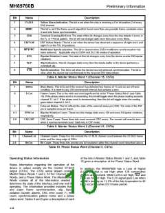
Bit
7-4
Name
Description
Unused
Keep at 0 for normal operation
3
2
1-0
A
B
C, D
These are the 4 signalling bits inserted in the appropriate channels of the DS1 stream being
output from the chip, when in ESF mode. In D3/D4 modes where there are only two signalling
bits, the values of C and D are ignored.
Table 7. Per Channel Control Word 2 Input at CSTi1
4-63

 MITEL [ MITEL NETWORKS CORPORATION ]