MH89760B
Preliminary Information
.
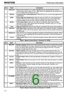
Bit
7
Name
YLALR
Description
Yellow Alarm Indication. This bit is set when the chip is receiving a 0 in bit position 2 of every
DS0 channel.
6
5
4
MIMIC
ERR
This bit is set if the frame search algorithm found more than one possible frame candidate when
it went into frame synchronization.
Terminal Framing Bit Error. The state of this bit changes every time the chip detects 4 errors in
the F or FPS bit pattern. The bit will not change state more than once every 96ms.
T
ESFYLW
ESF Yellow Alarm. This bit is set when the device has observed a sequence of eight one’s and
eight 0’s in the FDL bit positions.
3
2
1
MFSYNC
BPV
Multiframe Synchronization. This bit is cleared when D3/D4 multiframe synchronization has
been achieved. Applicable only in D3/D4 and SLC-96 modes of operation.
Bipolar Violation Count. The state of this bit changes every time the device counts 256 bipolar
violations.
SLIP
Slip Indication. This bit changes state every time the elastic buffer in the device performs a
controlled slip.
0
SYN
Synchronization. This bit is set when the device has not achieved synchronization. The bit is
clear when the device has synchronized to the received DS1 data stream.
Table 8. Master Status Word 1 (Channel 15, CSTo)
Description
Bit
7
Name
BlAlm
Blue Alarm. This bit is set if the receiver has detected two frames of 1’s and an out of frame
condition. It is reset by any 250 microsecond interval that contains a zero.
6
FrCnt
Frame Count. This is the ninth and most significant bit of the “Phase Status Word" (see Table
10). If the phase status word is incrementing, this bit will toggle when the phase reading exceeds
channel 31, bit 7. If the phase word is decrementing, then this bit will toggle when the reading
goes below channel 0, bit 0.
5
XSt
External Status. This bit reflects the state of the external status pin (XSt). The state of the XSt
pin is sampled once per frame.
4-3
2-0
BPVCnt
CRCCNT
Bipolar Violation Count. These two bits change state every 128 and every 64 bipolar violations,
respectively.
CRC Error Count. These three bits count received CRC errors. The counter will reset to zero
when it reaches terminal count. Valid only in ESF mode.
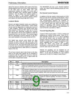
Table 9. Master Status Word 2 (Channel 31, CSTo)
Description
Bit
7-3
Name
ChannelCnt
Channel Count. These five bits indicate the ST-BUS channel count between the ST-BUS frame
pulse and the rising edge of E8Ko.
2-0
BitCnt
Bit Count. These three bits provide one bit resolution within the channel count described above.
Table 10. Phase Status Word (Channel 3, CSTo)
Operating Status Information
of the bits in Master Status Words 1 and 2, and Table
10 gives a description of the Phase Status Word.
Status Information regarding the operation of the
device is output serially via the Control ST-BUS
output (CSTo). The CSTo serial stream contains
Master Status Words 1 and 2, 24 Per Channel Status
Words, and a Phase Status Word. The Master Status
Words contain all of the information needed to
determine the state of the interface and how well it is
operating. The information provided includes frame
and super frame synchronization, slip, bipolar
violation counter, alarms, CRC error count, FT error
count, synchronization pattern mimic and a phase
status word. Tables 8 and 9 give a description of each
In addition, the MH89760B has a Loss of Signal
(LOS) pin that is set High when 128 consecutive
ZEROs are received. While LOS is set High, RxA and
RxB are forced High. The LOS signal goes Low when
a ONEs density on 12.5% of the bits (equivalent to 48
bits) occurs in a two DS1 frame period.
4-64

 MITEL [ MITEL NETWORKS CORPORATION ]