MH89760B
Preliminary Information
.
Bit
7
Name
Description
Debounce
When set the received A, B, C and D signalling bits are reported directly in the per
channel status words output at CSTo. When clear, the signalling bits are debounced for
6 to 9 ms before they are placed on CSTo.
6
5
TSPZCS
B8ZS
Transparent Zero Code Suppression. When this bit is set, no zero code suppression is
implemented.
Binary Eight Zero Suppression. When this bit is set, B8ZS zero code suppression is
enabled. When clear, bit 7 in data channels containing all zeros is forced high before
being transmitted on the DS1 side. This bit is inactive if the TSPZCS bit is set.
4
8kHSel
8 kHz Output Select. When set, the E8Ko pin is held high. When clear, the E8Ko
generates an 8 kHz output derived from the extracted 1.544 MHz clock or C1.5i clock
(see Pin Description for E8Ko).
3
2
XCtl
External Control Pin. When set, the XCtl pin is held high. When clear, XCtl is held low.
ESFYLW
ESF Yellow Alarm. Valid only in ESF mode. When set, a sequence of eight 1’s followed
by eight 0’s is sent in the FDL bit positions. When clear, the FDL bit contains data input at
the TxFDL pin.
1
0
Robbed bit
YLALR
When this bit is set, robbed bit signalling is disabled on all DS0 transmit channels. When
clear, A, B, C and D signalling bits are inserted into bit position 8 of all DS0 channels in
every 6th frame.
Yellow Alarm. When set, bit 2 of all DS0 channels is set low. When clear, bit 2 operates
normally.
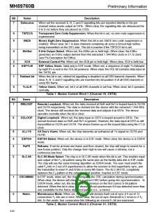
Table 1. Master Control Word 1 (Channel 15, CSTi0)
Bit
7
Name
Description
RMLOOP
Remote Loopback. When set, the data received at RxR and RxT is looped back to OUTB
and OUTA respectively. The data is clocked into the device with the extracted 1.544 MHz
clock. The device still monitors the received data and outputs it at DSTo. The device
operates normally when the bit is clear.
6
DGLOOP
Digital Loopback. When set, the data input on DSTi is looped around to DSTo. The
normal received data on RxR and RxT is ignored. However, the data input at DSTi is still
transmitted on OUTA and OUTB. The device frames up on the looped data using the C1.5i
clock.
5
4
3
ALL1'S
ESF/D4
ReFR
All One’s Alarm. When set, the chip transmits an unframed all 1's signal on OUTA and
OUTB.
ESF/D4 Select. When set, the device is in ESF mode. When clear, the device is in D3/D4
mode.
Reframe. If set for at least one frame and then cleared, the chip will begin to search for a
new frame position. Only the change from high to low will cause a reframe, not a
continuous low level.
2
SLC-96
SLC-96 Mode Select. The chip is in SLC-96 mode when this bit is set. This enables input
and output of the FS bit pattern using the same pins as the facility data link in ESF mode.
The chip will use the same framing algorithm as D3/D4 mode. The user must insert the
valid FS bits in 2 out of 6 superframes to allow the receiver to find superframe sync, and
the transmitter to insert A and B bits in every 6th frame. The SLC-96 FDL completely
replaces the FS pattern in the outgoing S bit position. Inactive in ESF mode.
1
0
CRC/MIMIC In ESF mode, when set, the chip disregards the CRC calculation during synchronization.
When clear, the device will check for a correct CRC before going into synchronization. In
D3/D4 mode, when set, the device will synchronize on the first correct S-bit pattern
detected. When this bit is clear, the device will not synchronize if it has detected more than
one candidate for the frame alignment pattern (i.e., a mimic).
Maint.
Maintenance Mode. When set, the device will declare itself out-of-sync if 4 out of 12
consecutive FT bits are in error. When clear, the out-of-sync threshold is 2 errors in 4 FT
bits. In this mode, four consecutive bits following an errored FT bit are examined.
Table 2. Master Control Word 2 (Channel 31, CSTi0)
4-60

 MITEL [ MITEL NETWORKS CORPORATION ]