Preliminary Information
MH89760B
MH89760B
MH89761
OUTA
+12V
TR1
EIT
EIR
R1
1:
1:
L2
Transmit
Data
TxT
TxR
:0.5
S1
L1
C2
EA
EB
S2
S3
C1
OUTB
EC
SW
S4
RCLT
RCHT
RCLR
S5
S6
S7
RCHR
Ti
TL
RL
Ri
E1.5o
RxA
RxB
RxT
TR2
1:
Rx
Line
Extracted
Clock
:1
Receiver
Received
Data
1:
RxR
+5V
V
0-150’
CLOSE
OPEN
OPEN
OPEN
OPEN
OPEN
OPEN
150-450’
OPEN
450-655’
OPEN
DD
S1
S2
S4
S4
S5
S6
S7
CLOSE
OPEN
OPEN
CLOSE
OPEN
CLOSE
OPEN
CLOSE
CLOSE
OPEN
CLOSE
OPEN
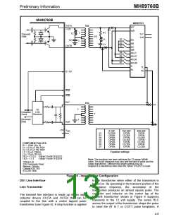
COMPONENT VALUES:
R1 = 150Ω 1% 14
W
C1 = 0.01 µF 5% 250V
C2 = 0.47 µF 5% 100V
L1 = 33 µH 130mA
Equalizer settings
L2 = 33 µH 165 mA
TR1 = 1:1:0.5 Filtran* Part # TFS2573
TR2 = 1:1:1
Filtran* Part # TFS2574
Note: The equalizer has been optimized for 22 gauge ABAM
cable. The exact distances may vary with the type of cable and the
output transformer. Different line length settings may be
*Filtran Ltd.
229 Colonnade Road
Nepean, Ontario
Canada K2E 7K3
613-226-1626
required if a transformer other than the Filtran TFS2573 is used.
Figure 6 - Input/Output Configuration
to the transformer when either of the transistors is
DS1 Line Interface
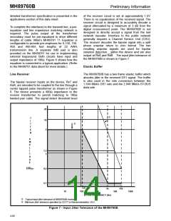
Line Transmitter
turned on. By operating in the transient portion of the
inductance response, the secondary of the
transformer produces an almost square pulse. The
capacitor and inductor on the center tap of the
transmit transformer shown in Figure 6 suppress
transients in the 12 volt supply. The series RLC
across the output of the transformer shape the pulse
to meet the AT & T or CCITT pulse templates. A
The transmit line interface is made up of two open
collector drivers (OUTA and OUTB) that can be
coupled to the line with a center tapped pulse
transformer (see Figure 6). A step function is applied
4-67

 MITEL [ MITEL NETWORKS CORPORATION ]