Preliminary Information
MH89760B
†
†
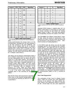
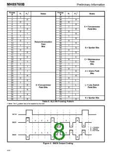
Frame #
FPS FDL CRC
Signalling
Frame #
FT
FS
Signalling
1
2
3
4
5
6
7
8
9
10
11
12
13
14
15
16
17
18
19
20
21
22
23
24
X
1
2
3
4
5
6
7
8
9
1
CB1
0
0
1
1
1
0
X
0
1
0
1
0
0
X
CB2
X
A
B
C
D
A
0
X
CB3
X
10
11
12
1
B
X
Table 4. D3/D4 Framer
† These signalling bits are only valid if the robbed bit signalling is
active.
CB4
X
0
Standard D3/D4 framing is enabled when bit 4 of
Master Control Word 2 is reset (logic 0). In this mode
the device searches for and inserts the framing
pattern shown in Table 4. This mode only supports
AB bit signalling, and does not contain a CRC check.
X
CB5
X
1
X
CB6
X
The CRC/MIMIC bit in Master Control Word 2, when
set high, allows the device to synchronize in the
presence of a mimic. If this bit is reset, the device will
not synchronize in the presence of a mimic. (Also
refer to section on Framing Algorithm.)
1
Table 3. ESF Frame Pattern
† These signalling bits are only valid if the robbed bit signalling is
active.
During synchronization the receiver locks on to the
incoming frame, calculates the CRC and compares it
to the CRC received in the next multiframe. The
device will not declare itself to be in synchro-
nization unless a valid framing pattern in the S-bit is
detected and a correct CRC is received. The CRC
check in this case provides protection against false
framing. The CRC check can be turned off by setting
bit 1 in Master Control Word 2.
In the D3/D4 mode the device can also be made
compatible with SLC-96 by setting bit two of Master
Control Word 2. This allows the user to insert and
extract the signalling framing pattern on the DS1 bit
stream using the FDL input and output pins. The
user must format this 4 kbits of information externally
to meet all of the requirements of the SLC-96
specification (see Table 5). The device multiplexes
and demultiplexes this information into the proper
position. This mode of operation can also be used for
any other application that uses all or part of the
signalling framing pattern. As long as the serial
stream clocked into the TxFDL contains two proper
sets of consecutive synchronization bits (as shown in
Table 5 for frames 1 to 24), the device will be
able to insert and extract the A, B signalling bits.
The TxSF pin should be held high in this mode.
Superframe boundaries cannot be defined by a pulse
on this input. The RxSF output functions normally
and indicates the superframe boundaries based on
the synchronization pattern in the FS received bit
position.
The device can be forced to resynchronize itself. If
Bit 3 in Master Control Word 2 is set for one frame
and then subsequently reset, the device will start to
search for a new frame position. The decision to
reframe is made by the user’s system processor on
the basis of the status conditions detected in the
received master status words. This may include
consideration of the number of errors in the received
CRC in conjunction with an indication of the
presence of a mimic. When the device attains
synchronization the mimic bit in Master Status Word
1 is set if the device found another possible
candidate when it was searching for the framing
pattern.
Zero Code Suppression
Note that the device will resynchronize automatically
if the errors in the terminal framing pattern (FT or
FPS) exceed the threshold set with bit 0 in Master
Control Word 2.
The combination of bits 5 and 6 in Master Control
Word 1 allow one of three zero code suppression
schemes to be selected. The three choices are:
none, binary 8 zero suppression (B8ZS), or jammed
bit (bit 7 forced high). No zero code suppression
4-61

 MITEL [ MITEL NETWORKS CORPORATION ]