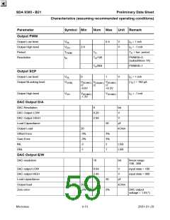
SDA 9380 - B21
Preliminary Data Sheet
Recommended operating conditions
Parameter
Symbol Min
Nom Max
Unit Remark
Input voltage data insertion
V
2.5
1.8
V
FBL2L = 0
FBL2L = 1
i-y
Dark current input DCI for cut off and white level control
Low input voltage
0
V
control bit RDCI=0
control bit RDCI=1
1.8
2.7
V
Full range input voltage
Maximum input current
Input RGB matrices
V
I
10
mA
V
> V
i-DCImax
i-DCI dd
PAL/SECAM mode
RGB matrix coefficients:
R = Y - V
0.19
0.51
U = - (B - Y)
V = - (R - Y)
P
P
u
v
G = Y + P U + P V
u
v
B = Y - U
NTSC/Jap mode
RGB matrix coefficients:
R = Y + J U + J V
U = - (B - Y)
V = - (R - Y)
J
J
J
J
J
0.068
−=1.38
0.15
0.46
−=1
ur
ur
vr
vr
G = Y + J U + J V
ug
vg
ug
vg
ub
B = Y + J
U
ub
NTSC/US mode
RGB matrix coefficients:
R = Y + A U + A V
U = - (B - Y)
V = - (R - Y)
A
A
A
A
A
A
0.12
−=1.32
0.25
0.42
−=1.08
0.035
ur
ur
vr
vr
G = Y + A U + A V
ug
vg
ug
vg
ub
vb
B = Y + A U + A V
ub
vb
HDTV mode (according to SMPTE Standard 274M and EIA-770.3-A)
RGB matrix coefficients:
U = P’ =
= 0.539 (B - Y)
H
H
H
H
1.575
B
vr
R = Y + H V
−=0.187
−=0.468
1.856
vr
ug
vg
ub
G = Y + H U + H V
V = P’ =
ug
vg
R
B = Y + H
U
= 0.635 (R - Y)
ub
Internal RGB matrices
See PAL/SECAM mode
Internal colour difference matrices
See PAL/SECAM mode
Micronas
8-47
2001-01-29

 MICRONAS [ MICRONAS ]