‡
Pre lim in a ry
MT9V012 - 1/6-In ch VGA CMOS Dig it a l Im a g e Se n so r
Me ch a n ica l Sp e cifica t io n s
Me ch a n ica l Sp e cifica t io n s
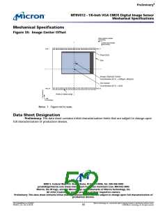
Fig u re 35: Im a g e Ce n t e r Offse t
Pixel column number
increasing
Pixel row number
increasing
Pad 1
Pad 17
Pixel (0,0)
Die
Image (Optical) Center
Coordinates (X,Y) = (220µm, 667µm)
Die Center
Coordinates (X,Y) = (0,0)
Pad 18
Pad 34
Pads (2 sides only)
X increasing
Notes: 1. Figure not to scale.
Da t a Sh e e t De sig n a t io n
Pre lim in a ry: This data sheet contains initial characterization limits that are subject to change upon
full characterization of production devices.
®
8000 S. Fe d e ra l Wa y, P.O. Bo x 6, Bo ise , ID 83707-0006, Te l: 208-368-3900
p ro d m kt g @m icro n .co m w w w .m icro n .co m Cu st o m e r Co m m e n t Lin e : 800-932-4992
Micro n , t h e M lo g o , a n d t h e Micro n lo g o a re t ra d e m a rks o f Micro n Te ch n o lo g y, In c.
All o t h e r t ra d e m a rks a re t h e p ro p e rt y o f t h e ir re sp e ct ive o w n e rs.
Pre lim in a ry: Th is d a t a sh e e t co n t a in s in it ia l ch a ra ct e riza t io n lim it s t h a t a re su b je ct t o ch a n g e u p o n fu ll ch a ra ct e riza t io n o f
p ro d u ct io n d e vice s.
PDF: 814eb99f/Source: 8175e929
MT9V012_2.fm - Rev. B 2/05 EN
Micron Technology, Inc., reserves the right to change products or specifications without notice.
©2004 Micron Technology, Inc. All rights reserved.
52

 MICRON [ MICRON TECHNOLOGY ]