2 MEG x 16
ASYNC/PAGE/BURST FLASH MEMORY
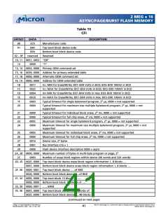
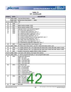
Table 15
CFI (continued)
OFFSET
DATA
DESCRIPTION
37, 38 0020, 0000 Top boot block device ……64KB
0000, 0001 Bottom boot block device ……64KB
39, 3A 0050, 0052 “PR”
3B
3C
3D
0049
0030
0031
“I”
Major version number, ASCII
Minor version number, ASCII
3E
3F
40
41
00E6
0003
0000
0000
Optional Feature and Command Support
Bit 0 Chip erase supported no = 0
Bit 1 Suspend erase supported = yes = 1
Bit 2 Suspend program supported = yes = 1
Bit 3 Chip lock/unlock supported = no = 0
Bit 4 Queued erase supported = no = 0
Bit 5 Instant individual block locking supported = yes = 1
Bit 6 Protection bits supported = yes = 1
Bit 7 Page mode read supported = yes = 1
Bit 8 Synchronous read supported = no = 0
Bit 9 Simultaneous operation supported = yes = 1
42
0001
Program supported after erase suspend = yes
43, 44 0003, 0000 Bit 0 block lock status active = yes; Bit 1 block lock down active = yes
45
46
47
0018
00C0
0001
VCC supply optimum, 00 = not supported, Bit7–Bit4 Volts in BCD; Bit3–Bit0 100mV in BCD
VPP supply optimum, 00 = not supported, Bit7–Bit4 Volts in BCD; Bit3–Bit0 100mV in BCD
Number of protection register fields in JEDEC ID space
48, 49 0080, 0000 Lock bytes LOW address, lock bytes HIGH address
4A, 4B 0003, 0003 2n factory programmed bytes, 2n user programmable bytes
4C
0003
Background Operation
0000 = Not used
0001 = 4% block split
0002 = 12% block split
0003 = 25% block split
0004 = 50% block split
4D
0072
Burst Mode Type
0000 = No burst mode
00x1 = 4 words MAX
00x2 = 8 words MAX
00x3 = 16 words MAX
001x = Linear burst, and/or
002x = Interleaved burst, and/or
004x = Continuous burst
4E
4F
0002
0000
Page Mode Type
0000 = No page mode
0001 = 4-word page
0002 = 8-word page
0003 = 16-word page
0004 = 32-word page
Not used
2 Meg x 16 Async/Page/Burst Flash Memory
MT28F322D20FH_4.p65 – Rev. 4, Pub. 7/02
Micron Technology, Inc., reserves the right to change products or specifications without notice.
©2002, Micron Technology, Inc.
42

 MICRON [ MICRON TECHNOLOGY ]