2 MEG x 16
ASYNC/PAGE/BURST FLASH MEMORY
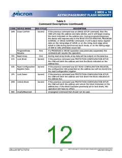
Table 5
Command Descriptions (continued)
CODE DEVICE MODE
BUS CYCLE
DESCRIPTION
D0h Erase Confirm
Second
If the previous command was an ERASE SETUP command, then the
CSM will close the address and data latches, and it will begin erasing
the block indicated on the address pins. During programming/erase,
the device will respond only to the READ STATUS REGISTER, PROGRAM
SUSPEND, or ERASE SUSPEND commands. It will output status register
data on the rising edge of ADV#, or on the rising clock edge when
ADV# is LOW during synchronous burst mode, or on the falling edge
of OE# or CE#, whichever occurs last.
Program/Erase
Resume
First
If a PROGRAM or ERASE operation was previously suspended, this
command will resume the operation.
FFh Read Array
01h Lock Block
First
During read array mode, array data will be output on the data bus.
Second
If the previous command was PROTECTION CONFIGURATION SETUP,
the CSM will latch the address and lock the block indicated on the
address bus.
03h Read Configuration Second
Register Data
If the previous command was SET READ CONFIGURATION REGISTER,
the configuration bits presented on the address bus will be stored into
the read configuration register.
2Fh Lock Down
Second
Second
If the previous command was PROTECTION CONFIGURATION SETUP,
the CSM will latch the address and lock down the block indicated on
the address bus.
D0h Unlock Block
If the previous command was PROTECTION CONFIGURATION SETUP,
the CSM will latch the address and unlock the block indicated on the
address bus. If the block had been previously set to lock down, this
operation will have no effect.
00h Invalid/Reserved
Unassigned command that should not be used.
2 Meg x 16 Async/Page/Burst Flash Memory
MT28F322D20FH_4.p65 – Rev. 4, Pub. 7/02
Micron Technology, Inc., reserves the right to change products or specifications without notice.
12
©2002, Micron Technology, Inc.

 MICRON [ MICRON TECHNOLOGY ]