PIC24FJ64GA104 FAMILY
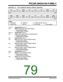
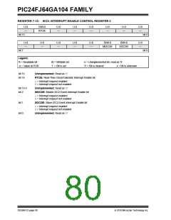
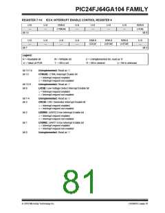
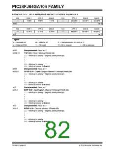
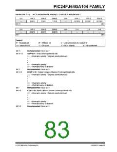
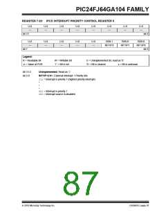
REGISTER 7-16: IPC1: INTERRUPT PRIORITY CONTROL REGISTER 1
U-0
—
R/W-1
T2IP2
R/W-0
T2IP1
R/W-0
T2IP0
U-0
—
R/W-1
R/W-0
R/W-0
OC2IP2
OC2IP1
OC2IP0
bit 15
bit 8
U-0
—
R/W-1
IC2IP2
R/W-0
IC2IP1
R/W-0
IC2IP0
U-0
—
U-0
—
U-0
—
U-0
—
bit 7
bit 0
Legend:
R = Readable bit
W = Writable bit
‘1’ = Bit is set
U = Unimplemented bit, read as ‘0’
‘0’ = Bit is cleared x = Bit is unknown
-n = Value at POR
bit 15
Unimplemented: Read as ‘0’
T2IP<2:0>: Timer2 Interrupt Priority bits
bit 14-12
111= Interrupt is priority 7 (highest priority interrupt)
•
•
•
001= Interrupt is priority 1
000= Interrupt source is disabled
bit 11
Unimplemented: Read as ‘0’
bit 10-8
OC2IP<2:0>: Output Compare Channel 2 Interrupt Priority bits
111= Interrupt is priority 7 (highest priority interrupt)
•
•
•
001= Interrupt is priority 1
000= Interrupt source is disabled
bit 7
Unimplemented: Read as ‘0’
bit 6-4
IC2IP<2:0>: Input Capture Channel 2 Interrupt Priority bits
111= Interrupt is priority 7 (highest priority interrupt)
•
•
•
001= Interrupt is priority 1
000= Interrupt source is disabled
bit 3-0
Unimplemented: Read as ‘0’
2010 Microchip Technology Inc.
DS39951C-page 83

 MICROCHIP [ MICROCHIP ]