PIC24FJ64GA104 FAMILY
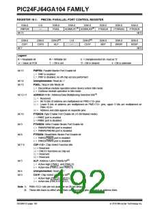
REGISTER 18-1: PMCON: PARALLEL PORT CONTROL REGISTER (CONTINUED)
bit 2
BEP: Byte Enable Polarity bit
1= Byte enable active-high (PMBE)
0= Byte enable active-low (PMBE)
bit 1
WRSP: Write Strobe Polarity bit
For Slave modes and Master Mode 2 (PMMODE<9:8> = 00,01,10):
1= Write strobe active-high (PMWR)
0= Write strobe active-low (PMWR)
For Master Mode 1 (PMMODE<9:8> = 11):
1= Enable strobe active-high (PMENB)
0= Enable strobe active-low (PMENB)
bit 0
RDSP: Read Strobe Polarity bit
For Slave modes and Master Mode 2 (PMMODE<9:8> = 00,01,10):
1= Read strobe active-high (PMRD)
0= Read strobe active-low (PMRD)
For Master Mode 1 (PMMODE<9:8> = 11):
1= Read/write strobe active-high (PMRD/PMWR)
0= Read/write strobe active-low (PMRD/PMWR)
Note 1: PMA<10:2> bits are not available on 28-pin devices.
2: These bits have no effect when their corresponding pins are used as address lines.
2010 Microchip Technology Inc.
DS39951C-page 193

 MICROCHIP [ MICROCHIP ]