PIC24FJ64GA104 FAMILY
Key features of the PMP module include:
18.0 PARALLEL MASTER PORT
(PMP)
• Up to 16 Programmable Address Lines
• One Chip Select Line
Note:
This data sheet summarizes the features
• Programmable Strobe Options:
of this group of PIC24F devices. It is not
intended to be a comprehensive reference
source. For more information, refer to the
“PIC24F Family Reference Manual”,
Section 13. “Parallel Master Port
(PMP)” (DS39713).
- Individual Read and Write Strobes or;
- Read/Write Strobe with Enable Strobe
• Address Auto-Increment/Auto-Decrement
• Programmable Address/Data Multiplexing
• Programmable Polarity on Control Signals
• Legacy Parallel Slave Port Support
• Enhanced Parallel Slave Support:
- Address Support
The Parallel Master Port (PMP) module is a parallel,
8-bit I/O module, specifically designed to communicate
with a wide variety of parallel devices, such as commu-
nication peripherals, LCDs, external memory devices
and microcontrollers. Because the interface to parallel
peripherals varies significantly, the PMP is highly
configurable.
- 4-Byte Deep Auto-Incrementing Buffer
• Programmable Wait States
• Selectable Input Voltage Levels
Note:
A number of the pins for the PMP are not
present on PIC24FJ64GA1 family devices.
Refer to the specific device’s pinout to
determine which pins are available.
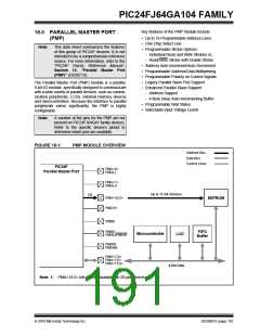
FIGURE 18-1:
PMP MODULE OVERVIEW
Address Bus
Data Bus
Control Lines
PIC24F
Parallel Master Port
PMA<0>
PMALL
PMA<1>
PMALH
Up to 11-Bit Address
(1)
PMA<10:2>
PMCS1
EEPROM
PMBE
PMRD
PMRD/PMWR
FIFO
Buffer
Microcontroller
LCD
PMWR
PMENB
PMD<7:0>
PMA<7:0>
PMA<15:8>
8-Bit Data
Note 1: PMA<10:2> bits are not available on 28-pin devices.
2010 Microchip Technology Inc.
DS39951C-page 191

 MICROCHIP [ MICROCHIP ]