PIC24FJ64GA104 FAMILY
REGISTER 17-2: UxSTA: UARTx STATUS AND CONTROL REGISTER (CONTINUED)
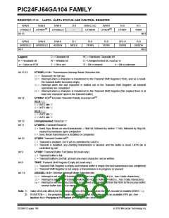
bit 5
bit 4
bit 3
bit 2
bit 1
ADDEN: Address Character Detect bit (bit 8 of received data = 1)
1= Address Detect mode is enabled. If 9-bit mode is not selected, this does not take effect.
0= Address Detect mode is disabled
RIDLE: Receiver Idle bit (read-only)
1= Receiver is Idle
0= Receiver is active
PERR: Parity Error Status bit (read-only)
1= Parity error has been detected for the current character (character at the top of the receive FIFO)
0= Parity error has not been detected
FERR: Framing Error Status bit (read-only)
1= Framing error has been detected for the current character (character at the top of the receive FIFO)
0= Framing error has not been detected
OERR: Receive Buffer Overrun Error Status bit (clear/read-only)
1= Receive buffer has overflowed
0= Receive buffer has not overflowed (clearing a previously set OERR bit (1 0transition) will reset
the receiver buffer and the RSR to the empty state
bit 0
URXDA: Receive Buffer Data Available bit (read-only)
1= Receive buffer has data, at least one more character can be read
0= Receive buffer is empty
Note 1: Value of bit only affects the transmit properties of the module when the IrDA encoder is enabled (IREN = 1).
2: If UARTEN = 1, the peripheral inputs and outputs must be configured to an available RPn pin. See
Section 10.4 “Peripheral Pin Select (PPS)” for more information.
2010 Microchip Technology Inc.
DS39951C-page 189

 MICROCHIP [ MICROCHIP ]