PIC24FJ64GA104 FAMILY
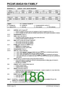
REGISTER 17-1: UxMODE: UARTx MODE REGISTER
R/W-0
UARTEN(1)
bit 15
U-0
—
R/W-0
USIDL
R/W-0
IREN(2)
R/W-0
U-0
—
R/W-0
UEN1
R/W-0
UEN0
RTSMD
bit 8
R/W-0, HC
WAKE
R/W-0
R/W-0, HC
ABAUD
R/W-0
RXINV
R/W-0
BRGH
R/W-0
R/W-0
R/W-0
LPBACK
PDSEL1
PDSEL0
STSEL
bit 7
bit 0
Legend:
HC = Hardware Clearable bit
W = Writable bit
R = Readable bit
-n = Value at POR
U = Unimplemented bit, read as ‘0’
‘0’ = Bit is cleared x = Bit is unknown
‘1’ = Bit is set
bit 15
UARTEN: UARTx Enable bit(1)
1= UARTx is enabled; all UARTx pins are controlled by UARTx as defined by UEN<1:0>
0= UARTx is disabled; all UARTx pins are controlled by port latches; UARTx power consumption is minimal
bit 14
bit 13
Unimplemented: Read as ‘0’
USIDL: Stop in Idle Mode bit
1= Discontinue module operation when the device enters Idle mode
0= Continue module operation in Idle mode
bit 12
bit 11
IREN: IrDA® Encoder and Decoder Enable bit(2)
1= IrDA encoder and decoder are enabled
0= IrDA encoder and decoder are disabled
RTSMD: Mode Selection for UxRTS Pin bit
1= UxRTS pin is in Simplex mode
0= UxRTS pin is in Flow Control mode
bit 10
Unimplemented: Read as ‘0’
UEN<1:0>: UARTx Enable bits
bit 9-8
11= UxTX, UxRX and BCLKx pins are enabled and used; UxCTS pin is controlled by port latches
10= UxTX, UxRX, UxCTS and UxRTS pins are enabled and used
01= UxTX, UxRX and UxRTS pins are enabled and used; UxCTS pin is controlled by port latches
00= UxTX and UxRX pins are enabled and used; UxCTS and UxRTS/BCLKx pins are controlled by
port latches
bit 7
WAKE: Wake-up on Start Bit Detect During Sleep Mode Enable bit
1= UARTx will continue to sample the UxRX pin; interrupt generated on falling edge; bit cleared in
hardware on following rising edge
0= No wake-up is enabled
bit 6
bit 5
LPBACK: UARTx Loopback Mode Select bit
1= Enable Loopback mode
0= Loopback mode is disabled
ABAUD: Auto-Baud Enable bit
1= Enable baud rate measurement on the next character – requires reception of a Sync field (55h);
cleared in hardware upon completion
0= Baud rate measurement is disabled or completed
bit 4
RXINV: Receive Polarity Inversion bit
1= UxRX Idle state is ‘0’
0= UxRX Idle state is ‘1’
Note 1: If UARTEN = 1, the peripheral inputs and outputs must be configured to an available RPn pin. See
Section 10.4 “Peripheral Pin Select (PPS)” for more information.
2: This feature is only available for the 16x BRG mode (BRGH = 0).
DS39951C-page 186
2010 Microchip Technology Inc.

 MICROCHIP [ MICROCHIP ]