PIC24FJ64GA104 FAMILY
16.1 Communicating as a Master in a
Single Master Environment
16.0 INTER-INTEGRATED CIRCUIT
2
(I C™)
The details of sending a message in Master mode
Note:
This data sheet summarizes the features
depends on the communications protocol for the device
being communicated with. Typically, the sequence of
events is as follows:
of this group of PIC24F devices. It is not
intended to be a comprehensive reference
source. For more information, refer to the
“PIC24F Family Reference Manual”,
Section 24. “Inter-Integrated Circuit™
(I2C™)” (DS39702).
1. Assert a Start condition on SDAx and SCLx.
2. Send the I2C device address byte to the slave
with a write indication.
The Inter-Integrated Circuit (I2C) module is a serial
interface useful for communicating with other peripheral
or microcontroller devices. These peripheral devices
may be serial EEPROMs, display drivers, A/D
Converters, etc.
3. Wait for and verify an Acknowledge from the
slave.
4. Send the first data byte (sometimes known as
the command) to the slave.
5. Wait for and verify an Acknowledge from the
slave.
The I2C module supports these features:
6. Send the serial memory address low byte to the
slave.
• Independent master and slave logic
• 7-bit and 10-bit device addresses
• General call address as defined in the I2C protocol
7. Repeat steps 4 and 5 until all data bytes are
sent.
• Clock stretching to provide delays for the
processor to respond to a slave data request
8. Assert a Repeated Start condition on SDAx and
SCLx.
• Both 100 kHz and 400 kHz bus specifications.
• Configurable address masking
9. Send the device address byte to the slave with
a read indication.
• Multi-Master modes to prevent loss of messages
in arbitration
10. Wait for and verify an Acknowledge from the
slave.
• Bus Repeater mode, allowing the acceptance of
all messages as a slave regardless of the address
11. Enable master reception to receive serial
memory data.
• Automatic SCL
12. Generate an ACK or NACK condition at the end
of a received byte of data.
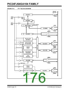
A block diagram of the module is shown in Figure 16-1.
13. Generate a Stop condition on SDAx and SCLx.
2010 Microchip Technology Inc.
DS39951C-page 175

 MICROCHIP [ MICROCHIP ]