PIC24FJ64GA104 FAMILY
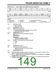
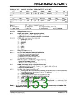
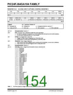
REGISTER 13-1: ICxCON1: INPUT CAPTURE x CONTROL REGISTER 1
U-0
—
U-0
—
U-0
—
U-0
—
R/W-0
R/W-0
R/W-0
R/W-0
ICSIDL
ICTSEL2
ICTSEL1
ICTSEL0
bit 15
bit 8
U-0
—
R/W-0
ICI1
R/W-0
ICI0
R-0, HCS
ICOV
R-0, HCS
ICBNE
R/W-0
ICM2(1)
R/W-0
ICM1(1)
R/W-0
ICM0(1)
bit 7
bit 0
Legend:
HCS = Hardware Clearable/Settable bit
R = Readable bit
-n = Value at POR
W = Writable bit
‘1’ = Bit is set
U = Unimplemented bit, read as ‘0’
‘0’ = Bit is cleared x = Bit is unknown
bit 15-14
bit 13
Unimplemented: Read as ‘0’
ICSIDL: Input Capture x Module Stop in Idle Control bit
1= Input capture module halts in CPU Idle mode
0= Input capture module continues to operate in CPU Idle mode
bit 12-10
ICTSEL<2:0>: Input Capture Timer Select bits
111= System clock (FOSC/2)
110= Reserved
101= Reserved
100= Timer1
011= Timer5
010= Timer4
001= Timer2
000= Timer3
bit 9-7
bit 6-5
Unimplemented: Read as ‘0’
ICI<1:0>: Select Number of Captures per Interrupt bits
11= Interrupt on every fourth capture event
10= Interrupt on every third capture event
01= Interrupt on every second capture event
00= Interrupt on every capture event
bit 4
ICOV: Input Capture x Overflow Status Flag bit (read-only)
1= Input capture overflow occurred
0= No input capture overflow occurred
bit 3
ICBNE: Input Capture x Buffer Empty Status bit (read-only)
1= Input capture buffer is not empty, at least one more capture value can be read
0= Input capture buffer is empty
bit 2-0
ICM<2:0>: Input Capture Mode Select bits(1)
111= Interrupt mode: input capture functions as interrupt pin only when device is in Sleep or Idle mode
(rising edge detect only, all other control bits are not applicable)
110= Unused (module disabled)
101= Prescaler Capture mode: capture on every 16th rising edge
100= Prescaler Capture mode: capture on every 4th rising edge
011= Simple Capture mode: capture on every rising edge
010= Simple Capture mode: capture on every falling edge
001= Edge Detect Capture mode: capture on every edge (rising and falling); ICI<1:0 bits do not control
interrupt generation for this mode
000= Input capture module turned off
Note 1: The ICx input must also be configured to an available RPn pin. For more information, see Section 10.4
“Peripheral Pin Select (PPS)”.
2010 Microchip Technology Inc.
DS39951C-page 153

 MICROCHIP [ MICROCHIP ]