PIC24FJ64GA104 FAMILY
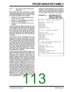
The assembly syntax of the PWRSAV instruction is
shown in Example 9-1.
9.0
POWER-SAVING FEATURES
Note:
This data sheet summarizes the features
of this group of PIC24F devices. It is not
intended to be a comprehensive reference
source. For more information, refer to the
“PIC24F Family Reference Manual”,
Section 39. “Power-Saving Features
with Deep Sleep” (DS39727).
Note: SLEEP_MODE and IDLE_MODE are
constants defined in the assembler
include file for the selected device.
Sleep and Idle modes can be exited as a result of an
enabled interrupt, WDT time-out or a device Reset.
When the device exits these modes, it is said to
“wake-up”.
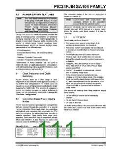
The PIC24FJ64GA104 family of devices provides the
ability to manage power consumption by selectively
managing clocking to the CPU and the peripherals. In
general, a lower clock frequency and a reduction in the
number of circuits being clocked constitutes lower
consumed power. All PIC24F devices manage power
consumption in four different ways:
9.2.1
SLEEP MODE
Sleep mode has these features:
• The system clock source is shut down. If an
on-chip oscillator is used, it is turned off.
• The device current consumption will be reduced
to a minimum provided that no I/O pin is sourcing
current.
• Clock Frequency
• Instruction-Based Sleep, Idle and Deep Sleep
modes
• The I/O pin directions and states are frozen.
• The Fail-Safe Clock Monitor does not operate
during Sleep mode since the system clock source
is disabled.
• Software Controlled Doze mode
• Selective Peripheral Control in Software
Combinations of these methods can be used to
selectively tailor an application’s power consumption,
while still maintaining critical application features, such
as timing-sensitive communications.
• The LPRC clock will continue to run in Sleep
mode if the WDT or RTCC with LPRC as clock
source is enabled.
• The WDT, if enabled, is automatically cleared
prior to entering Sleep mode.
9.1
Clock Frequency and Clock
Switching
• Some device features or peripherals may
continue to operate in Sleep mode. This includes
items, such as the input change notification on the
I/O ports, or peripherals that use an external clock
input. Any peripheral that requires the system
clock source for its operation will be disabled in
Sleep mode.
PIC24F devices allow for a wide range of clock
frequencies to be selected under application control. If
the system clock configuration is not locked, users can
choose low-power or high-precision oscillators by simply
changing the NOSC bits. The process of changing a
system clock during operation, as well as limitations to
the process, are discussed in more detail in Section 8.0
“Oscillator Configuration”.
The device will wake-up from Sleep mode on any of
these events:
• On any interrupt source that is individually
enabled
9.2
Instruction-Based Power-Saving
Modes
• On any form of device Reset
• On a WDT time-out
PIC24F devices have two special power-saving modes
that are entered through the execution of a special
PWRSAVinstruction. Sleep mode stops clock operation
and halts all code execution; Idle mode halts the CPU
and code execution, but allows peripheral modules to
continue operation. Deep Sleep mode stops clock
operation, code execution and all peripherals except
RTCC and DSWDT. It also freezes I/O states and
removes power to SRAM and Flash memory.
On wake-up from Sleep, the processor will restart with
the same clock source that was active when Sleep
mode was entered.
EXAMPLE 9-1:
PWRSAV INSTRUCTION SYNTAX
PWRSAV
PWRSAV
BSET
#SLEEP_MODE
#IDLE_MODE
DSCON, #DSEN
#SLEEP_MODE
; Put the device into SLEEP mode
; Put the device into IDLE mode
; Enable Deep Sleep
PWRSAV
; Put the device into Deep SLEEP mode
2010 Microchip Technology Inc.
DS39951C-page 111

 MICROCHIP [ MICROCHIP ]