PIC18F2480/2580/4480/4580
24.9.2
TIME QUANTA
24.9.3
SYNCHRONIZATION SEGMENT
As already mentioned, the Time Quanta is a fixed unit
derived from the oscillator period and baud rate
prescaler. Its relationship to TBIT and the Nominal Bit
Rate is shown in Example 24-6.
This part of the bit time is used to synchronize the
various CAN nodes on the bus. The edge of the input
signal is expected to occur during the sync segment.
The duration is 1 TQ.
24.9.4
PROPAGATION SEGMENT
EXAMPLE 24-6:
CALCULATING TQ,
NOMINAL BIT RATE AND
NOMINAL BIT TIME
This part of the bit time is used to compensate for phys-
ical delay times within the network. These delay times
consist of the signal propagation time on the bus line
and the internal delay time of the nodes. The length of
the propagation segment can be programmed from
1 TQ to 8 TQ by setting the PRSEG<2:0> bits.
TQ (μs) = (2 * (BRP+1))/FOSC (MHz)
TBIT (μs) = TQ (μs) * number of TQ per bit interval
Nominal Bit Rate (bits/s) = 1/TBIT
This frequency (FOSC) refers to the effective
frequency used. If, for example, a 10 MHz external
signal is used along with a PLL, then the effective
frequency will be 4 x 10 MHz which equals 40 MHz.
24.9.5
PHASE BUFFER SEGMENTS
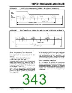
The phase buffer segments are used to optimally
locate the sampling point of the received bit within the
nominal bit time. The sampling point occurs between
Phase Segment 1 and Phase Segment 2. These
segments can be lengthened or shortened by the
resynchronization process. The end of Phase
Segment 1 determines the sampling point within a bit
time. Phase Segment 1 is programmable from 1 TQ to
8 TQ in duration. Phase Segment 2 provides a delay
before the next transmitted data transition and is also
programmable from 1 TQ to 8 TQ in duration. However,
due to IPT requirements, the actual minimum length of
Phase Segment 2 is 2 TQ, or it may be defined to be
equal to the greater of Phase Segment 1 or the
Information Processing Time (IPT). The sampling point
should be as late as possible or approximately 80% of
the bit time.
CASE 1:
For FOSC = 16 MHz, BRP<5:0> = 00h and
Nominal Bit Time = 8 TQ:
TQ = (2 * 1)/16 = 0.125 μs (125 ns)
TBIT = 8 * 0.125 = 1 μs (10-6s)
Nominal Bit Rate = 1/10-6 = 106 bits/s (1 Mb/s)
CASE 2:
For FOSC = 20 MHz, BRP<5:0> = 01h and
Nominal Bit Time = 8 TQ:
TQ = (2 * 2)/20 = 0.2 μs (200 ns)
TBIT = 8 * 0.2 = 1.6 μs (1.6 * 10-6s)
24.9.6
SAMPLE POINT
Nominal Bit Rate = 1/1.6 * 10-6s = 625,000 bits/s
The sample point is the point of time at which the bus
level is read and the value of the received bit is deter-
mined. The sampling point occurs at the end of Phase
Segment 1. If the bit timing is slow and contains many
TQ, it is possible to specify multiple sampling of the bus
line at the sample point. The value of the received bit is
determined to be the value of the majority decision of
three values. The three samples are taken at the sam-
ple point and twice before, with a time of TQ/2 between
each sample.
(625 Kb/s)
CASE 3:
For FOSC = 25 MHz, BRP<5:0> = 3Fh and
Nominal Bit Time = 25 TQ:
TQ = (2 * 64)/25 = 5.12 μs
TBIT = 25 * 5.12 = 128 μs (1.28 * 10-4s)
Nominal Bit Rate = 1/1.28 * 10-4
=
7813 bits/s
(7.8 Kb/s)
24.9.7
INFORMATION PROCESSING TIME
The Information Processing Time (IPT) is the time
segment starting at the sample point that is reserved
for calculation of the subsequent bit level. The CAN
specification defines this time to be less than or equal
to 2 TQ. The PIC18F2480/2580/4480/4580 devices
define this time to be 2 TQ. Thus, Phase Segment 2
must be at least 2 TQ long.
The frequencies of the oscillators in the different nodes
must be coordinated in order to provide a system wide
specified nominal bit time. This means that all oscilla-
tors must have a TOSC that is an integral divisor of TQ.
It should also be noted that although the number of TQ
is programmable from 4 to 25, the usable minimum is
8 TQ. There is no assurance that a bit time of less than
8 TQ in length will operate correctly.
© 2009 Microchip Technology Inc.
DS39637D-page 341

 MICROCHIP [ MICROCHIP ]