PIC18F2480/2580/4480/4580
The PIC18F2480/2580/4480/4580 devices are error-
the MCU if the bus remains Idle for 128 x 11 bit times.
If this is not desired, the error Interrupt Service Routine
should address this. The current Error mode of the
CAN module can be read by the MCU via the
COMSTAT register.
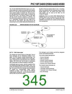
active if both error counters are below the error-passive
limit of 128. They are error-passive if at least one of the
error counters equals or exceeds 128. They go to bus-
off if the transmit error counter equals or exceeds the
bus-off limit of 256. The devices remain in this state
until the bus-off recovery sequence is finished. The
bus-off recovery sequence consists of 128 occurrences
of 11 consecutive recessive bits (see Figure 24-8).
Note that the CAN module, after going bus-off, will
recover back to error-active without any intervention by
Additionally, there is an Error State Warning flag bit,
EWARN, which is set if at least one of the error coun-
ters equals or exceeds the error warning limit of 96.
EWARN is reset if both error counters are less than the
error warning limit.
FIGURE 24-8:
ERROR MODES STATE DIAGRAM
Reset
Error
Active
-
RXERRCNT < 128 or
TXERRCNT < 128
128 occurrences of
11 consecutive
“recessive” bits
RXERRCNT ≥ 128 or
TXERRCNT ≥ 128
Error
-
Passive
TXERRCNT > 255
Bus-
Off
The interrupts can be broken up into two categories:
receive and transmit interrupts.
24.15 CAN Interrupts
The module has several sources of interrupts. Each of
these interrupts can be individually enabled or dis-
abled. The PIR3 register contains interrupt flags. The
PIE3 register contains the enables for the 8 main inter-
rupts. A special set of read-only bits in the CANSTAT
register, the ICODE bits, can be used in combination
with a jump table for efficient handling of interrupts.
The receive related interrupts are:
• Receive Interrupts
• Wake-up Interrupt
• Receiver Overrun Interrupt
• Receiver Warning Interrupt
• Receiver Error-Passive Interrupt
All interrupts have one source, with the exception of the
error interrupt and buffer interrupts in Mode 1 and 2. Any
of the error interrupt sources can set the error interrupt
flag. The source of the error interrupt can be determined
by reading the Communication Status register,
COMSTAT. In Mode 1 and 2, there are two interrupt
enable/disable and flag bits – one for all transmit buffers
and the other for all receive buffers.
The transmit related interrupts are:
• Transmit Interrupts
• Transmitter Warning Interrupt
• Transmitter Error-Passive Interrupt
• Bus-Off Interrupt
© 2009 Microchip Technology Inc.
DS39637D-page 345

 MICROCHIP [ MICROCHIP ]