PIC18F2480/2580/4480/4580
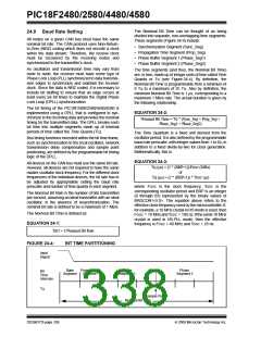
The Nominal Bit Time can be thought of as being
divided into separate, non-overlapping time segments.
These segments (Figure 24-4) include:
24.9 Baud Rate Setting
All nodes on a given CAN bus must have the same
nominal bit rate. The CAN protocol uses Non-Return-
to-Zero (NRZ) coding which does not encode a clock
within the data stream. Therefore, the receive clock
must be recovered by the receiving nodes and
synchronized to the transmitter’s clock.
• Synchronization Segment (Sync_Seg)
• Propagation Time Segment (Prop_Seg)
• Phase Buffer Segment 1 (Phase_Seg1)
• Phase Buffer Segment 2 (Phase_Seg2)
As oscillators and transmission time may vary from
node to node, the receiver must have some type of
Phase Lock Loop (PLL) synchronized to data transmis-
sion edges to synchronize and maintain the receiver
clock. Since the data is NRZ coded, it is necessary to
include bit stuffing to ensure that an edge occurs at
least every six bit times to maintain the Digital Phase
Lock Loop (DPLL) synchronization.
The time segments (and thus, the Nominal Bit Time)
are, in turn, made up of integer units of time called Time
Quanta or TQ (see Figure 24-4). By definition, the
Nominal Bit Time is programmable from a minimum of
8 TQ to a maximum of 25 TQ. Also by definition, the
minimum Nominal Bit Time is 1 μs, corresponding to a
maximum 1 Mb/s rate. The actual duration is given by
the following relationship.
The bit timing of the PIC18F2480/2580/4480/4580 is
implemented using a DPLL that is configured to syn-
chronize to the incoming data and provides the nominal
timing for the transmitted data. The DPLL breaks each
bit time into multiple segments made up of minimal
periods of time called the Time Quanta (TQ).
EQUATION 24-2:
Nominal Bit Time = TQ * (Sync_Seg + Prop_Seg +
Phase_Seg1 + Phase_Seg2)
The Time Quantum is a fixed unit derived from the
oscillator period. It is also defined by the programmable
baud rate prescaler, with integer values from 1 to 64, in
addition to a fixed divide-by-two for clock generation.
Mathematically, this is:
Bus timing functions executed within the bit time frame,
such as synchronization to the local oscillator, network
transmission delay compensation and sample point
positioning, are defined by the programmable bit timing
logic of the DPLL.
EQUATION 24-3:
All devices on the CAN bus must use the same bit rate.
However, all devices are not required to have the same
master oscillator clock frequency. For the different clock
frequencies of the individual devices, the bit rate has to
be adjusted by appropriately setting the baud rate
prescaler and number of time quanta in each segment.
TQ (μs) = (2 * (BRP+1))/FOSC (MHz)
or
TQ (μs) = (2 * (BRP+1)) * TOSC (μs)
where FOSC is the clock frequency, TOSC is the
corresponding oscillator period and BRP is an integer
(0 through 63) represented by the binary values of
BRGCON1<5:0>. The equation above refers to the
effective clock frequency used by the microcontroller. If,
for example, a 10 MHz crystal in HS mode is used, then
FOSC = 10 MHzandTOSC = 100 ns. If thesame 10 MHz
crystal is used in HS-PLL mode, then the effective
frequency is FOSC = 40 MHz and TOSC = 25 ns.
The Nominal Bit Rate is the number of bits transmitted
per second, assuming an ideal transmitter with an ideal
oscillator, in the absence of resynchronization. The
nominal bit rate is defined to be a maximum of 1 Mb/s.
The Nominal Bit Time is defined as:
EQUATION 24-1:
TBIT = 1/Nominal Bit Rate
FIGURE 24-4:
BIT TIME PARTITIONING
Input
Signal
Sync
Segment
Propagation
Segment
Phase
Segment 1
Phase
Segment 2
Bit
Time
Intervals
TQ
Sample Point
Nominal Bit Time
DS39637D-page 338
© 2009 Microchip Technology Inc.

 MICROCHIP [ MICROCHIP ]