PIC18F2480/2580/4480/4580
24.14.2 ACKNOWLEDGE ERROR
24.13 Bit Timing Configuration
Registers
In the Acknowledge field of a message, the transmitter
checks if the Acknowledge slot (which was sent out as
a recessive bit) contains a dominant bit. If not, no other
node has received the frame correctly. An Acknowl-
edge error has occurred, an error frame is generated
and the message will have to be repeated.
The Baud Rate Control registers (BRGCON1,
BRGCON2, BRGCON3) control the bit timing for the
CAN bus interface. These registers can only be modi-
fied when the PIC18F2480/2580/4480/4580 devices
are in Configuration mode.
24.14.3 FORM ERROR
24.13.1 BRGCON1
If a node detects a dominant bit in one of the four seg-
ments, including End-Of-Frame (EOF), interframe
space, Acknowledge delimiter or CRC delimiter, then a
form error has occurred and an error frame is
generated. The message is repeated.
The BRP bits control the baud rate prescaler. The
SJW<1:0> bits select the synchronization jump width in
terms of multiples of TQ.
24.13.2 BRGCON2
The PRSEG bits set the length of the propagation seg-
ment in terms of TQ. The SEG1PH bits set the length of
Phase Segment 1 in TQ. The SAM bit controls how
many times the RXCAN pin is sampled. Setting this bit
to a ‘1’ causes the bus to be sampled three times: twice
at TQ/2 before the sample point and once at the normal
sample point (which is at the end of Phase Segment 1).
The value of the bus is determined to be the value read
during at least two of the samples. If the SAM bit is set
to a ‘0’, then the RXCAN pin is sampled only once at
the sample point. The SEG2PHTS bit controls how the
length of Phase Segment 2 is determined. If this bit is
set to a ‘1’, then the length of Phase Segment 2 is
determined by the SEG2PH bits of BRGCON3. If the
SEG2PHTS bit is set to a ‘0’, then the length of Phase
Segment 2 is the greater of Phase Segment 1 and the
information processing time (which is fixed at 2 TQ for
the PIC18F2480/2580/4480/4580).
24.14.4 BIT ERROR
A bit error occurs if a transmitter sends a dominant bit
and detects a recessive bit, or if it sends a recessive bit
and detects a dominant bit, when monitoring the actual
bus level and comparing it to the just transmitted bit. In
the case where the transmitter sends a recessive bit
and a dominant bit is detected during the arbitration
field and the Acknowledge slot, no bit error is
generated because normal arbitration is occurring.
24.14.5 STUFF BIT ERROR
lf, between the Start-Of-Frame (SOF) and the CRC
delimiter, six consecutive bits with the same polarity are
detected, the bit stuffing rule has been violated. A stuff
bit error occurs and an error frame is generated. The
message is repeated.
24.14.6 ERROR STATES
24.13.3 BRGCON3
Detected errors are made public to all other nodes via
error frames. The transmission of the erroneous mes-
sage is aborted and the frame is repeated as soon as
possible. Furthermore, each CAN node is in one of the
three error states; “error-active”, “error-passive” or
“bus-off”, according to the value of the internal error
counters. The error-active state is the usual state
where the bus node can transmit messages and acti-
vate error frames (made of dominant bits) without any
restrictions. In the error-passive state, messages and
passive error frames (made of recessive bits) may be
transmitted. The bus-off state makes it temporarily
impossible for the node to participate in the bus
communication. During this state, messages can neither
be received nor transmitted.
The PHSEG2<2:0> bits set the length (in TQ) of Phase
Segment 2 if the SEG2PHTS bit is set to a ‘1’. If the
SEG2PHTS bit is set to a ‘0’, then the PHSEG2<2:0>
bits have no effect.
24.14 Error Detection
The CAN protocol provides sophisticated error
detection mechanisms. The following errors can be
detected.
24.14.1 CRC ERROR
With the Cyclic Redundancy Check (CRC), the trans-
mitter calculates special check bits for the bit
sequence, from the start of a frame until the end of the
data field. This CRC sequence is transmitted in the
CRC field. The receiving node also calculates the CRC
sequence using the same formula and performs a
comparison to the received sequence. If a mismatch is
detected, a CRC error has occurred and an error frame
is generated. The message is repeated.
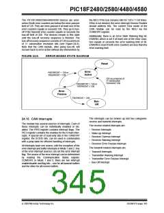
24.14.7 ERROR MODES AND ERROR
COUNTERS
The PIC18F2480/2580/4480/4580 devices contain two
error counters: the Receive Error Counter (RXERRCNT)
and the Transmit Error Counter (TXERRCNT). The
values of both counters can be read by the MCU. These
counters are incremented or decremented in
accordance with the CAN bus specification.
DS39637D-page 344
© 2009 Microchip Technology Inc.

 MICROCHIP [ MICROCHIP ]