PIC18F2480/2580/4480/4580
The High/Low-Voltage Detect Control register
23.0 HIGH/LOW-VOLTAGE DETECT
(Register 23-1) completely controls the operation of the
HLVD module. This allows the circuitry to be “turned
off” by the user under software control, which
minimizes the current consumption for the device.
(HLVD)
PIC18F2480/2580/4480/4580
devices
have
a
High/Low-Voltage Detect module (HLVD). This is a
programmable circuit that allows the user to specify
both a device voltage trip point and the direction of
change from that point. If the device experiences an
excursion past the trip point in that direction, an
interrupt flag is set. If the interrupt is enabled, the
program execution will branch to the interrupt vector
address and the software can then respond to the
interrupt.
The block diagram for the HLVD module is shown in
Figure 23-1.
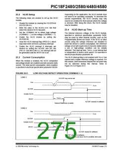
REGISTER 23-1: HLVDCON: HIGH/LOW-VOLTAGE DETECT CONTROL REGISTER
R/W-0
U-0
—
R-0
R/W-0
R/W-0
HLVDL3(1)
R/W-1
HLVDL2(1)
R/W-0
HLVDL1(1)
R/W-1
HLVDL0(1)
VDIRMAG
IRVST
HLVDEN
bit 7
bit 0
Legend:
R = Readable bit
-n = Value at POR
W = Writable bit
‘1’ = Bit is set
U = Unimplemented bit, read as ‘0’
‘0’ = Bit is cleared x = Bit is unknown
bit 7
VDIRMAG: Voltage Direction Magnitude Select bit
1= Event occurs when voltage equals or exceeds trip point (HLVDL<3:0>)
0= Event occurs when voltage equals or falls below trip point (HLVDL<3:0>)
bit 6
bit 5
Unimplemented: Read as ‘0’
IRVST: Internal Reference Voltage Stable Flag bit
1= Indicates that the voltage detect logic will generate the interrupt flag at the specified voltage range
0= Indicates that the voltage detect logic will not generate the interrupt flag at the specified voltage
range and the HLVD interrupt should not be enabled
bit 4
HLVDEN: High/Low-Voltage Detect Power Enable bit
1= HLVD enabled
0= HLVD disabled
bit 3-0
HLVDL<3:0>: High/Low-Voltage Detection Limit bits(1)
1111= External analog input is used (input comes from the HLVDIN pin)
1110= 4.48V-4.69V
1101= 4.23V-4.43V
1100= 4.01V-4.20V
1011= 3.81V-3.99V
1010= 3.63V-3.80V
1001= 3.46V-3.63V
1000= 3.31V-3.47V
0111= 3.05V-3.19V
0110= 2.82V-2.95V
0101= 2.72V-2.85V
0100= 2.54V-2.66V
0011= 2.38V-2.49V
0010= 2.31V-2.42V
0001= 2.18V-2.28V
0000= 2.12V-2.22V
Note 1: HLVDL<3:0> modes that result in a trip point below the valid operating voltage of the device are not tested.
© 2009 Microchip Technology Inc.
DS39637D-page 273

 MICROCHIP [ MICROCHIP ]