PIC18F2480/2580/4480/4580
Depending on the application, the HLVD module does
not need to be operating constantly. To decrease the
current requirements, the HLVD circuitry may only
need to be enabled for short periods where the voltage
is checked. After doing the check, the HLVD module
may be disabled.
23.2 HLVD Setup
The following steps are needed to set up the HLVD
module:
1. Disable the module by clearing the HLVDEN bit
(HLVDCON<4>).
2. Write the value to the HLVDL<3:0> bits that
select the desired HLVD trip point.
23.4 HLVD Start-up Time
3. Set the VDIRMAG bit to detect high voltage
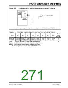
The internal reference voltage of the HLVD module,
specified in electrical specification parameter D420,
may be used by other internal circuitry, such as the
Programmable Brown-out Reset. If the HLVD or other
circuits using the voltage reference are disabled to
lower the device’s current consumption, the reference
voltage circuit will require time to become stable before
a low or high-voltage condition can be reliably
detected. This start-up time, TIRVST, is an interval that
is independent of device clock speed. It is specified in
electrical specification parameter 36.
(VDIRMAG = 1) or low voltage (VDIRMAG = 0).
4. Enable the HLVD module by setting the
HLVDEN bit.
5. Clear the HLVD interrupt flag (PIR2<2>), which
may have been set from a previous interrupt.
6. Enable the HLVD interrupt if interrupts are
desired by setting the HLVDIE and GIE bits
(PIE<2> and INTCON<7>). An interrupt will not
be generated until the IRVST bit is set.
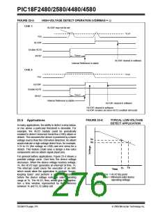
The HLVD interrupt flag is not enabled until TIRVST has
expired and a stable reference voltage is reached. For
this reason, brief excursions beyond the set point may
not be detected during this interval. Refer to
Figure 23-2 or Figure 23-3.
23.3 Current Consumption
When the module is enabled, the HLVD comparator
and voltage divider are enabled and will consume static
current. The total current consumption, when enabled,
is specified in electrical specification parameter D022B.
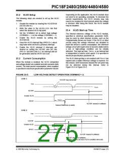
FIGURE 23-2:
LOW-VOLTAGE DETECT OPERATION (VDIRMAG = 0)
CASE 1:
HLVDIF may not be set
VDD
VLVD
HLVDIF
Enable HLVD
IRVST
TIRVST
HLVDIF cleared in software
Internal Reference is stable
CASE 2:
VDD
VLVD
HLVDIF
Enable HLVD
TIRVST
IRVST
Internal Reference is stable
HLVDIF cleared in software
HLVDIF cleared in software,
HLVDIF remains set since HLVD condition still exists
© 2009 Microchip Technology Inc.
DS39637D-page 275

 MICROCHIP [ MICROCHIP ]