PIC18F2480/2580/4480/4580
The module is enabled by setting the HLVDEN bit.
Each time that the HLVD module is enabled, the
circuitry requires some time to stabilize. The IRVST bit
is a read-only bit and is used to indicate when the circuit
is stable. The module can only generate an interrupt
after the circuit is stable and IRVST is set.
level at which the device detects a high or low-voltage
event, depending on the configuration of the module.
When the supply voltage is equal to the trip point, the
voltage tapped off of the resistor array is equal to the
internal reference voltage generated by the voltage
reference module. The comparator then generates an
interrupt signal by setting the HLVDIF bit.
The VDIRMAG bit determines the overall operation of
the module. When VDIRMAG is cleared, the module
monitors for drops in VDD below a predetermined set
point. When the bit is set, the module monitors for rises
in VDD above the set point.
The trip point voltage is software programmable to any
one of 16 values. The trip point is selected by
programming the HLVDL<3:0> bits (HLVDCON<3:0>).
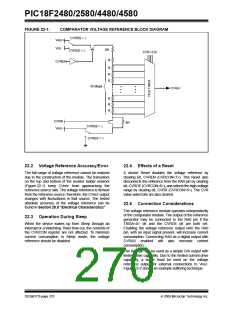
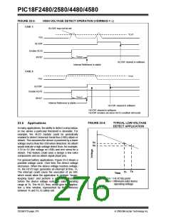
The HLVD module has an additional feature that allows
the user to supply the trip voltage to the module from an
external source. This mode is enabled when bits,
HLVDL<3:0>, are set to ‘1111’. In this state, the com-
parator input is multiplexed from the external input pin,
HLVDIN. This gives users flexibility because it allows
them to configure the High/Low-Voltage Detect interrupt
to occur at any voltage in the valid operating range.
23.1 Operation
When the HLVD module is enabled, a comparator uses
an internally generated reference voltage as the set
point. The set point is compared with the trip point
where each node in the resistor divider represents a
trip point voltage. The “trip point” voltage is the voltage
FIGURE 23-1:
HLVD MODULE BLOCK DIAGRAM (WITH EXTERNAL INPUT)
Externally Generated
Trip Point
VDD
VDD
HLVDL<3:0>
HLVDCON
Register
HLVDIN
VDIRMAG
HLVDEN
HLVDIN
Set
HLVDIF
HLVDEN
BOREN
Internal Voltage
Reference
DS39637D-page 274
© 2009 Microchip Technology Inc.

 MICROCHIP [ MICROCHIP ]